
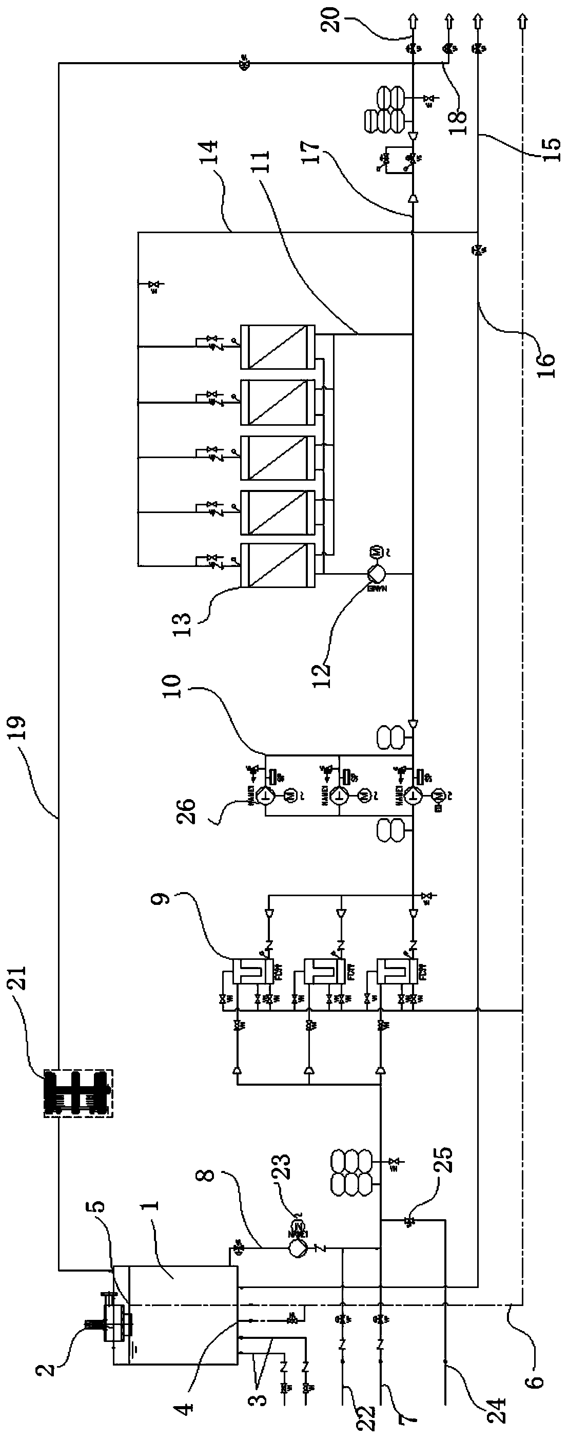
Leachate reverse osmosis treatment system and process flow thereof

A treatment system and reverse osmosis technology, which is applied in the field of leachate reverse osmosis treatment system and its process flow, can solve problems such as equipment and personal injury, membrane element damage, ecological environment damage, etc., to avoid the loss of chemicals and prevent foam overflow Effect

Pending Publication Date: 2019-10-01
CHONGQING GROUP SANFENG TECH
View PDF0 Cites 1 Cited by
  • Summary
  • Abstract
  • Description
  • Claims
  • Application Information

AI Technical Summary

Problems solved by technology

[0004] In the current STRO / DTRO reverse osmosis system, when the system is chemically cleaned, the water temperature will gradually rise due to the medium circulating in the pipeline. At that time, the water temperature will exceed the maximum water temperature that the membrane element can receive, and the membrane element will be subject to irreversible damage. damage, which reduces the interception rate of membrane elements to various ions and reduces the clear liquid rate of the system, thus affecting the normal operation of the entire equipment and causing huge economic losses, and may even cause damage to the ecological environment
[0005] And in the prior art scheme, the cleaning tank does not have a defoaming system. When the medicine is washed, especially when the alkali is washed, a large amount of foam will be generated, and this foam will quickly overflow and overflow to the equipment. A large amount of acidic or alkaline cleaning agents are corrosive and have a certain pungent smell. If they spill out, they will cause harm to equipment and people

Method used


Image

  • Leachate reverse osmosis treatment system and process flow thereof

Examples


Embodiment Construction

[0030] The following describes the implementation of the present invention through specific specific examples. Those skilled in the art can easily understand other advantages and effects of the present invention from the content disclosed in this specification. The present invention can also be implemented or applied through other different specific embodiments, and various details in this specification can also be modified or changed based on different viewpoints and applications without departing from the spirit of the present invention. It should be noted that the illustrations provided in the following embodiments are only illustrative to illustrate the basic concept of the present invention. In the case of no conflict, the following embodiments and features in the embodiments can be combined with each other.

[0031] Among them, the drawings are only used for exemplary description, and they are only schematic diagrams rather than physical drawings, and cannot be understood as...


PUM


Abstract

The invention belongs to the field of leachate treatment and relates to a leachate reverse osmosis treatment system and a process flow thereof. The system comprises a cleaning water tank, a defoamingsystem and a raw water inlet pipe; the cleaning water tank is communicated with a cleaning liquid pipe, the cleaning liquid pipe and the raw water inlet pipe are communicated with a safety filter, thesafety filter is communicated with a high-pressure pump station, and the high-pressure pump station is communicated with a circulating pipe; the circulating pipe is communicated with a clear liquid pipe and a concentrated liquid pipe, the clear liquid pipe is communicated with a clear liquid efflux branch pipe and a clear liquid returning branch pipe, and the concentrated liquid pipe is divided into three branches including a concentrated liquid efflux branch pipe, a concentrated liquid returning branch pipe and a concentrated liquid tank efflux branch pipe; the portion, close to the cleaningwater tank, of the concentrated liquid returning branch pipe is provided with a cooling system. The cooling system is added into the leachate reverse osmosis treatment system to cool a medium in order to protect a film element; a defoaming system is added into the leachate reverse osmosis treatment system to carry out defoaming treatment on generated foam in order to prevent the situation that the foam overflows and thus causes damage to equipment, personnel and the environment.

Description

Technical field [0001] The invention belongs to the field of leachate treatment, and relates to a percolate reverse osmosis treatment system and its technological process. Background technique [0002] The water quality of leachate is affected by the composition, scale, precipitation, climate and other factors of the garbage. Generally speaking, it has the following characteristics: large changes in water quality, high organic matter concentration, high SS content, high ammonia nitrogen content, and imbalanced nutrient element ratio, etc. Many features. At present, the treatment of leachate mostly adopts membrane separation technology. According to the water quality conditions of each project, through a variety of membrane separation technologies such as ultrafiltration, nanofiltration, roll reverse osmosis, network tube reverse osmosis, TUF softening membrane and material membrane, etc. To achieve advanced treatment of leachate. [0003] The composition of the leachate is comple...

Claims


Application Information

Patent Timeline
Patent Type & Authority Applications(China)
IPC IPC(8): C02F9/04B01D19/02C02F103/06
CPCC02F9/00B01D19/02C02F1/001C02F1/441C02F5/08C02F2303/14C02F2301/043C02F2103/06
Inventor 龙威张云孟刘洋雷东徐代平皮俊敏胥良陈果徐保贤陈艳王建齐友明韩帛锦
Owner CHONGQING GROUP SANFENG TECH
Learn More