Displacement amplifying tuning fork type micro-mechanical gyroscope based on lever effect

A technology of displacement amplification and mechanical gyroscope, which is applied in the direction of gyroscope/steering sensing equipment, gyro effect for speed measurement, instruments, etc., which can solve the problem of small improvement in processing circuit accuracy, low detection accuracy of micro-mechanical gyroscope, and difficulty in displacement detection Large and other problems, to achieve the effect of improving detection accuracy and sensitivity, improving detection sensitivity, and suppressing structural mechanical coupling

Active Publication Date: 2019-10-08
BEIJING INSTITUTE OF TECHNOLOGYGY
View PDF5 Cites 4 Cited by
  • Summary
  • Abstract
  • Description
  • Claims
  • Application Information

AI Technical Summary

Problems solved by technology

[0003] However, the displacement of the micromechanical gyroscope in the detection mode is very small. When detecting the rotation of 1° / s, the detection displacement is less than 1nm. Because the displacement is too small, the displacement detection is difficult and the mechanical sensitivity is low. Mechanical gyroscopes have low detection accuracy and can only achieve short-term tactical-level angle detection
[0005] The displacement of the micro-mechanical gyroscope in the detection mode is very small. When detecting the rotation of 1° / s, the detection displacement is less than 1nm. Because the displacement is too small, it is difficult to detect the displacement and the mechanical sensitivity is low, which leads to the existing micro-mechanical gyroscope. The accuracy of instrument detection is low and only short-term tactical angle detection can be realized
The accuracy and level of the current peripheral processing circuit has reached the limit, and the effect of improving the accuracy of the processing circuit is very small. Therefore, it is very important to improve the mechanical sensitivity of the micromachined gyroscope.

Method used


Image

  • Displacement amplifying tuning fork type micro-mechanical gyroscope based on lever effect
  • Displacement amplifying tuning fork type micro-mechanical gyroscope based on lever effect
  • Displacement amplifying tuning fork type micro-mechanical gyroscope based on lever effect

Examples


Embodiment Construction

[0037] In order to further understand the content, features and effects of the present invention, the following examples are given, and detailed descriptions are given below with reference to the accompanying drawings.

[0038] The structure of the present invention will be described in detail below in conjunction with the accompanying drawings.

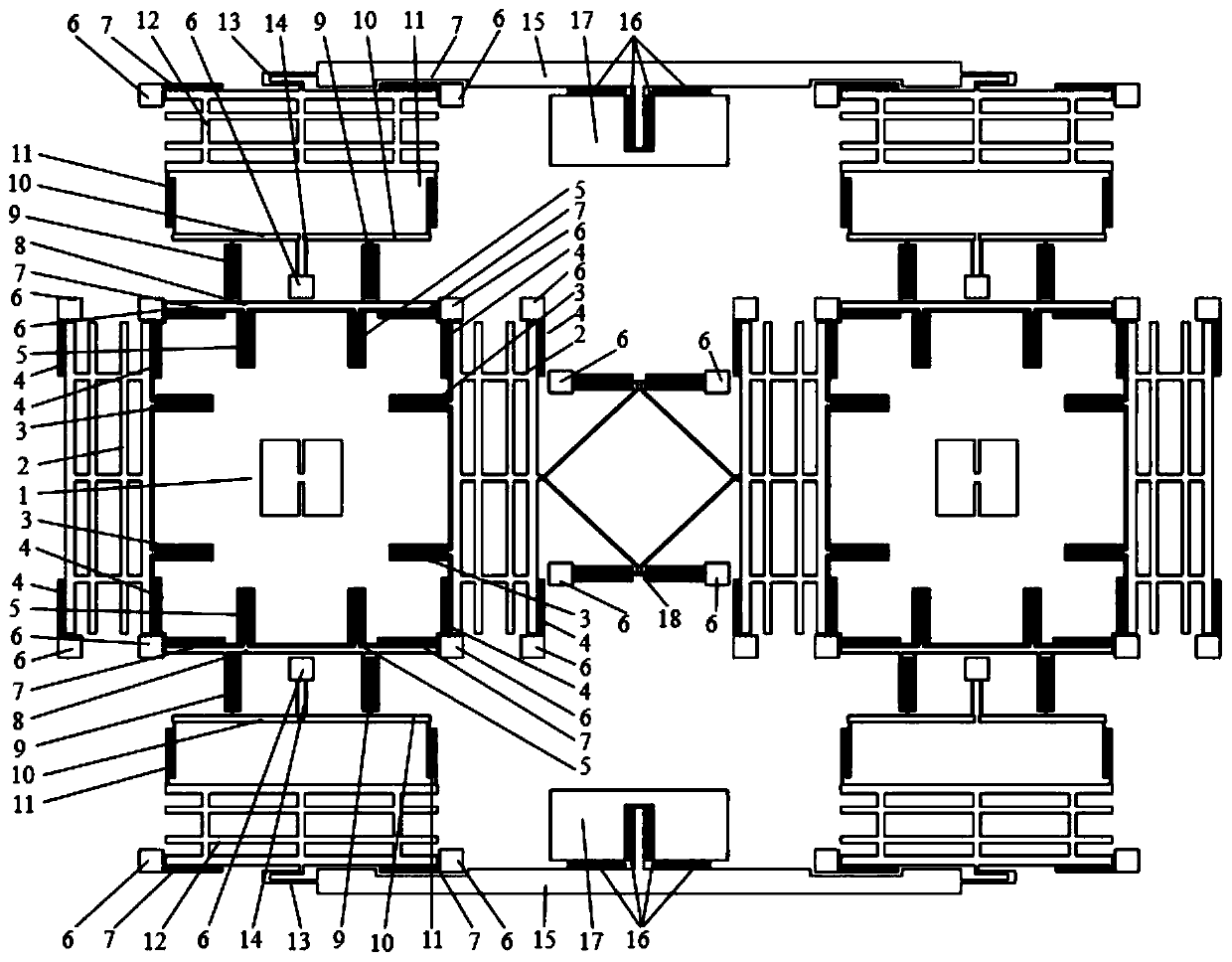
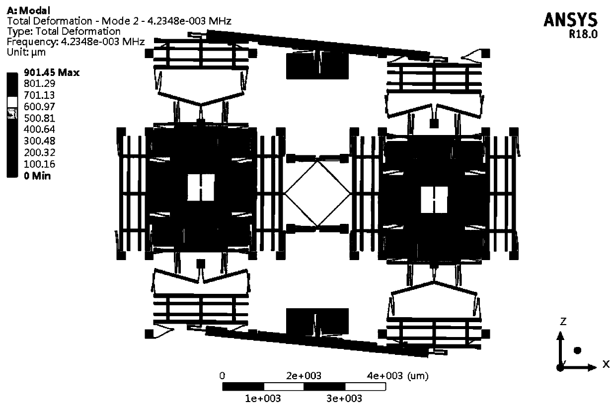
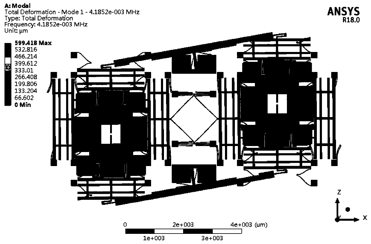
[0039] Such as figure 1 As shown, the lever effect-based displacement amplification tuning fork micromachined gyroscope provided by the embodiment of the present invention includes a glass substrate, metal electrodes, and a MEMS mechanical structure.

[0040] The silicon chip is bonded on the glass substrate, and the silicon chip on the glass substrate is photolithographically etched to form an anchor point, and the glass substrate is photoetched, and sputtered metal is peeled off to form a metal electrode;

[0041] The MEMS mechanical structure released by photolithographic deep etching on the silicon wafer is a fully decoupled ful...


PUM


Abstract

The invention, which belongs to the technical field of micromechanical systems, discloses a displacement amplifying tuning fork type micro-mechanical gyroscope based on a lever effect. Photoetching isperformed on a glass substrate and metal is sputtered, and a metal electrode is formed by stripping; a silicon wafer is bonded to glass substrate and photoetching deep etching is performed on the silicon wafer on the glass substrate to form an anchor point; and photoetching deep etching is performed on the silicon wafer to release an MEMS mechanical structure that is fully-decoupled fully-symmetric structural tuning fork structure. According to the invention, a flexible lever mechanism is arranged between the central mass block and the detection frame of the detection mode, the detection displacement of the central mass block is amplified and is transmitted to the detection frame, and the detection frame detects a capacitance change obviously. Meanwhile, secondary decoupling is realized by using the dead point effect of the lever and the decoupling property of the U-shaped force transmission beam, so that the orthogonal coupling is reduced and thus the higher sensitivity and higher resolution are realized.

Description

technical field [0001] The invention belongs to the technical field of micromechanical systems, in particular to a tuning fork micromechanical gyroscope based on lever effect displacement amplification. Background technique [0002] At present, the closest existing technology: micromachined gyroscope is an inertial sensor that measures angular velocity or angular displacement, and has achieved rapid development in the past three decades. Compared with traditional gyroscopes, micromachined gyroscopes have low cost , small size, light weight, low power consumption, mass production, easy digitization, intelligence and many other advantages. With the continuous improvement of the performance of micro-mechanical gyroscopes, micro-mechanical gyroscopes have been widely used in industrial fields such as automobile stability systems and anti-skid systems, robot attitude control, and some can be applied to small aircraft automatic control systems, radar stability control systems, Gu...

Claims


Application Information

Patent Timeline
IPC IPC(8): G01C19/5621G01C19/5614
CPCB81B2201/0242G01C19/5614G01C19/5621
Inventor 李泽章高世桥彭世刚刘海鹏金磊
Owner BEIJING INSTITUTE OF TECHNOLOGYGY
Why Eureka
Try Eureka