Sparse wireless energy transmission TRM design method and structure
A wireless energy transmission and design method technology, applied in computing, special data processing applications, instruments, etc., can solve the problems of not caring about the reduction of gain, limiting the flexibility of sparse arrays, and being unable to apply field distribution design, etc.
- Summary
- Abstract
- Description
- Claims
- Application Information
AI Technical Summary
Problems solved by technology
Method used
Image
Examples
Embodiment 1
[0080] Embodiment 1. Sparse wireless energy transmission TRM structure and design in free space
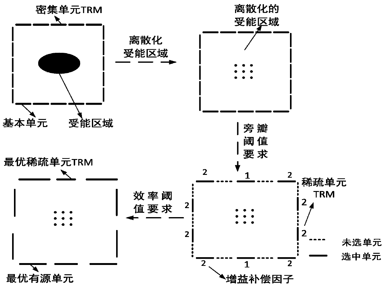
[0081] This embodiment provides a sparse wireless energy transmission TRM design method and structure, the schematic diagram of the design method is as follows figure 1 shown, including the following steps:
[0082] Step 1. Set dense unit TRM and energy transmission index
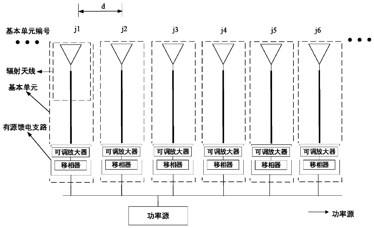
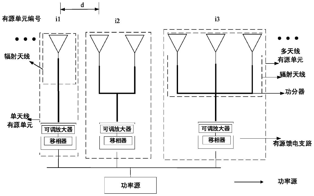
[0083] Set the dense unit TRM as an 8-element line array with equal spacing, and the numbers of the basic units are 1 to 8 from left to right; the powered antenna is 4 equally spaced units located in free space, 500mm away from the TRM array, and the central axis of the transceiver array same as Figure 4 shown. The basic unit of the dense unit TRM is a single-antenna active unit, which is formed by connecting the feed end of a single antenna unit to an active feed branch, such as Figure 5 shown. The transmitting and receiving antenna units are all microstrip patch antennas working at 2.45GHz, and the sp...
Embodiment 2
[0099] Embodiment 2. Sparse wireless energy transmission TRM structure and design in a scattering environment
[0100] Step 1. Set dense unit TRM and energy transmission index
[0101] Set the dense port TRM as an 8-element equidistant line array, the numbers are Ω={1,...,8}, N=8; the energy-receiving areas are four discrete ones located at a distance of 500mm from the TRM line array in the scattering environment Position, that is, the location of the receiving unit; the scatterers are six metal cylinders with a height of 50mm and a spacing of 110mm, located between the transceiver arrays and 200mm away from the normal direction of the TRM line array, such as Figure 9 shown. The basic unit of the dense unit TRM is a single-antenna active unit, which is formed by connecting the feed end of a single antenna to an active feed branch, such as Figure 5 shown. The transmitting and receiving antenna units are all microstrip patch antennas working at 2.45GHz, and the specific par...
PUM
 Abstract
Description
Claims
Application Information
 - R&D
- Intellectual Property
- Life Sciences
- Materials
- Tech Scout
- Unparalleled Data Quality
- Higher Quality Content
- 60% Fewer Hallucinations
Browse by: Latest US Patents, China's latest patents, Technical Efficacy Thesaurus, Application Domain, Technology Topic, Popular Technical Reports.
© 2025 PatSnap. All rights reserved.Legal|Privacy policy|Modern Slavery Act Transparency Statement|Sitemap|About US| Contact US: help@patsnap.com


