Marine diesel engine, engine control device and method
A diesel engine and control device technology, applied in engine control, engine components, machines/engines, etc., can solve problems such as cost increase and achieve stable denitrification treatment
- Summary
- Abstract
- Description
- Claims
- Application Information
AI Technical Summary
Problems solved by technology
Method used
Image
Examples
no. 1 approach
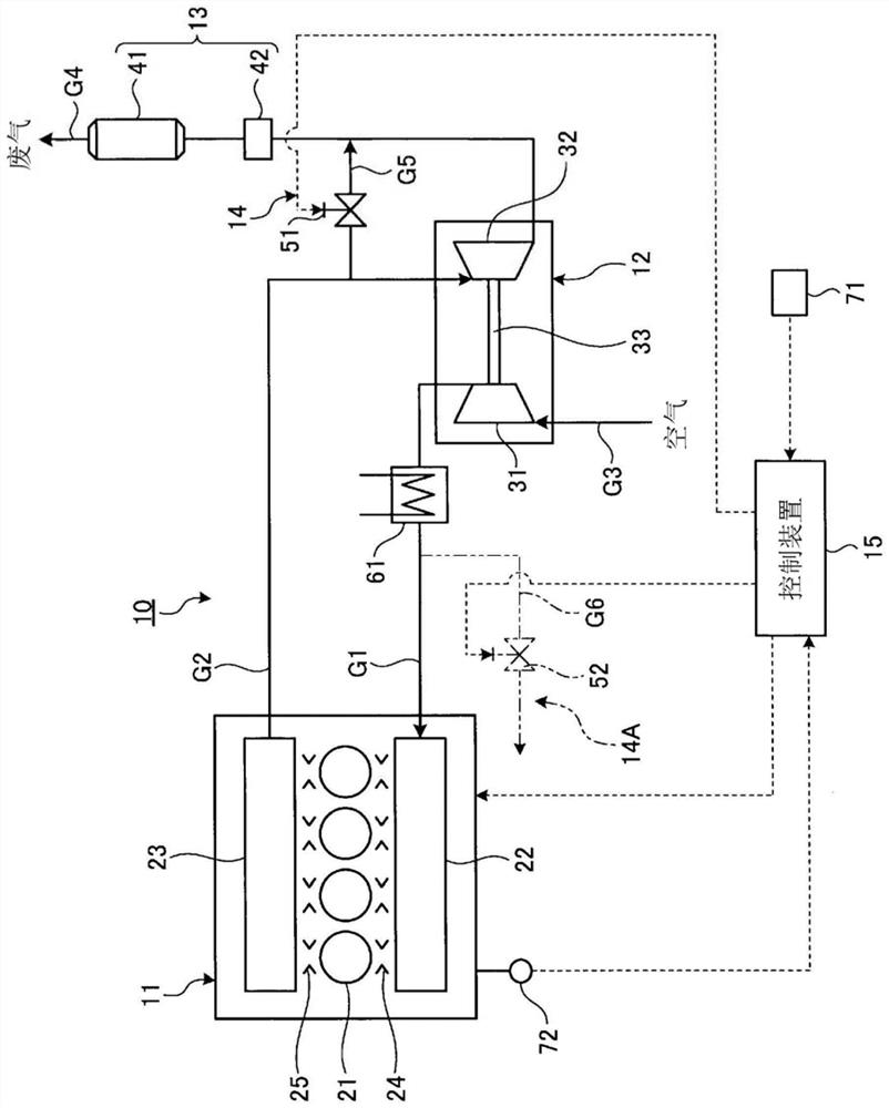
[0037] figure 1 It is a schematic configuration diagram showing the marine diesel engine of the first embodiment.
[0038] In the first embodiment, if figure 1 As shown, a marine diesel engine 10 includes an engine main body 11 , a supercharger 12 , an SCR denitrification device 13 , an exhaust gas temperature raising device 14 , and a control device 15 .
[0039]The engine main body 11 is a propulsion engine (main engine) that rotationally drives a propulsion propeller via a propeller shaft. The engine main body 11 is a single-flow scavenging type diesel engine, which is a two-stroke diesel engine, and the intake and exhaust flow in the cylinder is set to a single direction from the bottom to the top, thereby eliminating residual exhaust gas. The engine main body 11 includes: a plurality of cylinders (combustion chambers) 21 through which pistons move up and down; a scavenging manifold 22 communicating with each cylinder 21 ; and an exhaust manifold (exhaust static pressure...
no. 2 approach
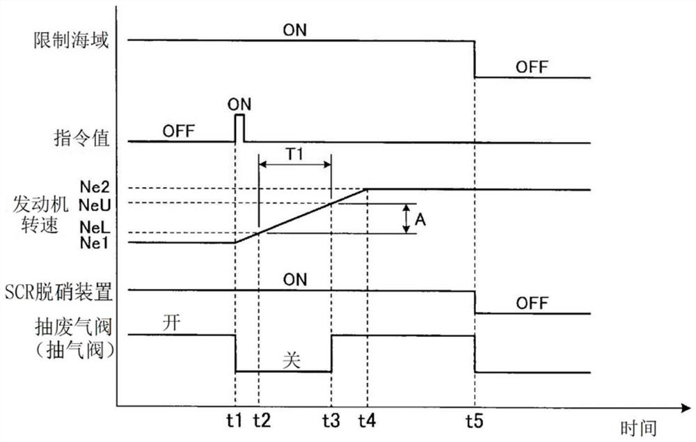
[0072] image 3 It is a timing chart showing the operation of the SCR denitration device in the marine diesel engine of the second embodiment. In addition, the basic structure of the marine diesel engine of this embodiment is substantially the same as that of the above-mentioned first embodiment. figure 1 In the following description, components having the same functions as those in the first embodiment described above are denoted by the same reference numerals and detailed description thereof will be omitted.
[0073] Such as figure 1 As shown, in the marine diesel engine of the second embodiment, the control device 15 stops the operation of the exhaust gas temperature raising device 14 ( 14A) when the current engine speed reaches the critical speed range A.
[0074] Such as figure 1 as well as image 3 As shown, when the sailing sea area of the ship is in the ECA (restricted sea area) (ON), the SCR denitrification device 13 works (ON) and the exhaust gas temperature ra...
no. 3 approach
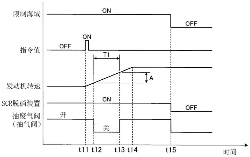
[0079] Figure 4 It is a timing chart showing the operation of the SCR denitration device in the marine diesel engine of the third embodiment. In addition, the basic structure of the marine diesel engine of this embodiment is substantially the same as that of the above-mentioned first embodiment. figure 1 In the following description, components having the same functions as those in the first embodiment described above are denoted by the same reference numerals and detailed description thereof will be omitted.
[0080] Such as figure 1 As shown, in the marine diesel engine of the third embodiment, the control device 15 sets the lower limit of the critical speed range A obtained by adding a preset margin value B to the lower limit value of the critical speed range A. The lower limit value of the critical speed range A is low, and when the current engine speed reaches the lower limit value of the margin, the exhaust gas temperature raising device 14 ( 14A) is stopped.
[0081...
PUM
 Abstract
Description
Claims
Application Information
 - R&D
- Intellectual Property
- Life Sciences
- Materials
- Tech Scout
- Unparalleled Data Quality
- Higher Quality Content
- 60% Fewer Hallucinations
Browse by: Latest US Patents, China's latest patents, Technical Efficacy Thesaurus, Application Domain, Technology Topic, Popular Technical Reports.
© 2025 PatSnap. All rights reserved.Legal|Privacy policy|Modern Slavery Act Transparency Statement|Sitemap|About US| Contact US: help@patsnap.com


