A Fault Tolerant Control Method for Heterogeneous Fleets Based on Variable Time Spacing Strategy
A time-spacing, fault-tolerant control technology, applied in non-electric variable control, two-dimensional position/channel control, vehicle position/route/height control, etc., can solve system instability, cannot guarantee traffic flow stability, cannot guarantee Queue stability and other issues to achieve the effect of ensuring stability and increasing critical traffic capacity
- Summary
- Abstract
- Description
- Claims
- Application Information
AI Technical Summary
Problems solved by technology
Method used
Image
Examples
Embodiment 1
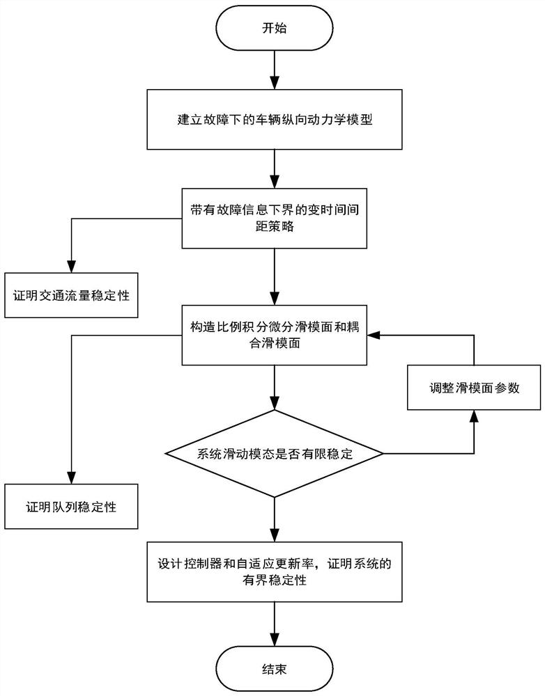
[0115] The specific process of step S1 is as follows:
[0116] S11. Define the dynamic model of the leading vehicle, as follows:
[0117]
[0118] where x0 (t), v 0 (t), a 0 (t) represent the position, speed and acceleration of the leading car respectively, and a 0 (t) represents the same given time function;
[0119] S12. Perform force analysis on the longitudinal motion of the vehicle to obtain the longitudinal dynamic model of the vehicle:
[0120]
[0121]
[0122]
[0123] where x i ,v i ,a i are the position, velocity and acceleration of vehicle i respectively; c i is the actuator input, f i (v i ,a i ) is a nonlinear function, and its function expression is as follows:
[0124]
[0125] Among them, τ i is the engine time constant, υ is the air mass constant, m i , A i , C di and d mi are the mass, cross-sectional area, drag coefficient and mechanical drag of vehicle i respectively; due to the mass m of the car i is uncertain, so the nonli...
Embodiment 2
[0136] On the basis of embodiment 1, the specific process of step S2 is as follows:
[0137] S21. Define the displacement tracking error as follows:
[0138]
[0139] Among them, δ i is the safety distance error between the i-th car and the i-1th car, γ i is a constant, L i is the length of vehicle i, Δ i-1,i is the safety distance between two vehicles, h represents the delay time of the fleet control system, σ represents the safety factor, A m is the expected maximum acceleration of the controlled vehicle, ρ i0 Represents the lower bound value of the actuator failure; thus it can be obtained that:
[0140]
[0141] Indicates that the initial value of the proposed variable time spacing strategy is zero in any case;
[0142] S22. Define the ideal inter-vehicle distance as follows:
[0143]
Embodiment 3
[0145] On the basis of embodiment 2, the specific process of step S3 is as follows:
[0146] S31. In order to make δ i It tends to be infinitely close to 0 in a finite time and guarantees the consistent stability of the queue, constructing a proportional-integral-differential sliding surface:
[0147]
[0148] Among them, K p ,K i ,K d represent proportional, integral and differential coefficients respectively;
[0149] S32. According to the transfer function G i (s) definition, construct δ i and δ i+1 The relationship between , defines the coupled sliding mode surface:
[0150]
[0151] where λ is the coupled sliding mode surface s i and s i+1 normal number of ; when s i When reaching the sliding surface, s i can also reach the sliding surface.
PUM
 Abstract
Description
Claims
Application Information
 - R&D
- Intellectual Property
- Life Sciences
- Materials
- Tech Scout
- Unparalleled Data Quality
- Higher Quality Content
- 60% Fewer Hallucinations
Browse by: Latest US Patents, China's latest patents, Technical Efficacy Thesaurus, Application Domain, Technology Topic, Popular Technical Reports.
© 2025 PatSnap. All rights reserved.Legal|Privacy policy|Modern Slavery Act Transparency Statement|Sitemap|About US| Contact US: help@patsnap.com


