Motor control module, actuator and electro-mechanical braking device

A technology of motor control and actuator, applied in the direction of motor control, connection with control/drive circuit, brake, etc., can solve the problems of low assembly efficiency, circuit board scrapping, circuit board occupation, etc., to improve assembly efficiency, Reduce the difficulty of assembly and meet the diverse effects

Active Publication Date: 2019-10-15
HALDEX VIE (SHANGHAI) ELECTROMECHANICAL BRAKE SYST CO LTD
View PDF15 Cites 3 Cited by
  • Summary
  • Abstract
  • Description
  • Claims
  • Application Information

AI Technical Summary

Problems solved by technology

[0004] For the above-mentioned motor control module, in the prior art, a plurality of connecting holes are arranged on the circuit board, and the pins of the capacitor pass through the connecting holes and are welded to the wiring circuit on the back of the circuit board. On the circuit board, a part of the area of ​​the circuit board is occupied by the capacitor bank, and the area occupied by the capacitor bank cannot accommodate other electronic components. Considering the layout of other electronic components on the circuit board, it is necessary to make these electronic components more densely distributed on the circuit board Or use a larger-sized circuit board to meet the circuit design requirements; in the circuit design process, not only the position of the capacitor bank must be reserved on the circuit board, but also the installation of other electronic components must be considered, which increases the difficulty of circuit design
In addition, this kind of motor control module not only has low production line assembly efficiency, but also errors in assembly operations may lead to direct scrapping of the circuit board

Method used


Image

  • Motor control module, actuator and electro-mechanical braking device
  • Motor control module, actuator and electro-mechanical braking device
  • Motor control module, actuator and electro-mechanical braking device

Examples


Embodiment approach 1

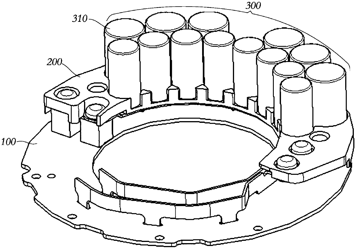
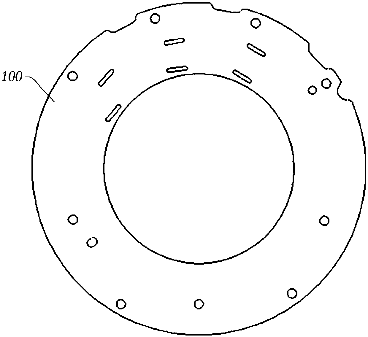
[0086] refer to figure 1 , the motor control module for the vehicle braking system proposed by the present invention includes: a circuit board 100, a capacitor group 300 and a conductive connector, wherein the capacitor group 300 includes a plurality of capacitors 310, and the plurality of capacitors 310 are respectively connected to the conductive The connecting piece forms a capacitor group 300 in which a plurality of capacitors 310 are electrically connected to each other through a conductive connecting piece. Keep a gap between. According to the purpose of the present invention: after the capacitor group 300 is connected to the circuit board 100 through a conductive connector, the capacitor group 300 and the circuit board 100 form a stacked structure. Except for the connection part with the circuit board 100, other parts of the conductive connector are relatively circuit The board 100 is in a suspended state, which enables the capacitor group 300 connected to the conducti...

Embodiment approach 2

[0109] The difference from Embodiment 1 is that in Embodiment 2, the capacitor bracket includes a first bracket and a second bracket formed separately, and the two ends of the body of the capacitor are respectively positioned on the first bracket and the second bracket, and the first bracket and the second bracket are respectively positioned. The structural design of the second bracket can refer to the capacitor bracket described in Embodiment 1. The capacitor is positioned according to the scheme described in Embodiment 1. Since the upper and lower ends of the capacitor are fixed by the bracket, the shaking of the capacitor can be better prevented. Better: the first bracket and the second bracket are fixedly connected to each other, such as screwed, to clamp and fix the capacitor group between the two, which can prevent the first bracket and the second bracket from being separated from each other, and the capacitor bracket can better position the capacitor Stablize.

[0110] ...

Embodiment approach 3

[0113] The difference from the first embodiment is that in the third embodiment, the motor control module further includes an extended connector, and the conductive connector and the circuit board are electrically connected through the extended connector. The expansion connector is not only used as an extension of the conductive connector, so that the conductive connector can be electrically connected to the connection point on the circuit board that is far away from the capacitor bank, but also can be used for the distribution of power transmission, and the electric energy of the capacitor bank is separately supplied to the circuit board. Other electronic components or circuits meet the power supply requirements of other components and circuits on the circuit board. For example, capacitor banks and conductive connectors are located in a specific area of ​​the circuit board. The electrical connection of electronic components and circuits to other areas of the circuit board.

...


PUM


Abstract

The invention discloses a motor control module, an actuator and an electro-mechanical braking device, belongs to the technical field of mechanical braking and solves the problems of insufficient spaceand large size of a circuit board due to direct connection between the circuit board and a capacitor in an existing motor control module. The motor control module comprises the circuit board; a capacitor group, which comprises a plurality of capacitors; and a conductive connecting piece, which is electrically connected with the plurality of capacitors, wherein the conductive connecting piece is electrically connected to the circuit board and is suspended relative to the circuit board to maintain a gap between the capacitor group and the circuit board. The area, originally occupied by the capacitor group, of the circuit board can hold other electronic components, so that the space, originally occupied by the capacitor group, of the circuit board is saved to install other electronic components, and installation of the other electronic components on the circuit board is not limited by the capacitor group; and under the condition of using the same number of components, a smaller circuit board can be used.

Description

【Technical field】 [0001] The invention relates to the technical field of mechanical braking, in particular to a motor control module for a vehicle braking system, an actuator with the motor control module and an electromechanical braking device using the actuator. 【Background technique】 [0002] An electromechanical brake device (EMB) usually has an actuator and a disc brake. The torque generated by the actuator acts on the brake caliper of the disc brake through a mechanical structure to realize the compression of the brake caliper and the brake disc. , so as to generate the required braking force. Compared with the traditional electro-hydraulic brake (EHB), the electro-mechanical brake device is easier to manufacture and assemble, the brake response speed is fast, the control performance is good, and it is easy to realize the brake-by-wire. The electro-hydraulic braking device is a big step forward of the traditional braking method. [0003] As the power source of the ele...

Claims


Application Information

Patent Timeline
Patent Type & Authority Applications(China)
IPC IPC(8): H02P29/00H01G4/002H01G4/38
CPCH02P29/00H01G4/002H01G4/38B60T13/74B60T13/741F16D2121/24H02K11/33H02K3/522H02K3/50H02K2203/03H02K2211/03F16D65/18F16D65/22F16D2131/02F16D2250/0076H01G4/224
Inventor 吴刚安德斯·林奎斯特安德斯·尼尔森宋增来董显斌费宜波
Owner HALDEX VIE (SHANGHAI) ELECTROMECHANICAL BRAKE SYST CO LTD
Why Eureka
Try Eureka