
Angiographic catheter with adjustable end bending angle

A technology of bending angle and bending tube, which is applied in the medical field, can solve the problems of poor image quality, difficulty, and difficulty of contrast images, and achieve the effects of reducing X-ray radiation time, high work and operation efficiency, and saving operation time

Pending Publication Date: 2019-10-18
THE FIRST AFFILIATED HOSPITAL OF ZHENGZHOU UNIV
View PDF3 Cites 1 Cited by
  • Summary
  • Abstract
  • Description
  • Claims
  • Application Information

AI Technical Summary

Problems solved by technology

[0006] There are certain defects in the specific operation process in the above-mentioned patent documents: in the specific operation process of the document CN201520230005.3, the bending degree of the end part cannot be adjusted, and the guide wire is inserted by relying on the fracture degree of the tube wall itself. There is great difficulty in the actual operation process; in the document of CN201220201944.1, in the specific operation process, the catheter head end is slightly bent to the direction of the traction wire cavity, and the position of the catheter head end can be adjusted when pulling a traction wire. However, in the process of setting and adjusting the angle, since the tip of the catheter is slightly bent in the direction of the lumen of the pulling wire, in the process of pulling the pulling wire, when the catheter is bent toward the position of the blood vessel that needs to be bent, it will be in the process of bending In fact, an angle that hinders access is formed at the bending intersection of blood vessels, and it is very difficult to achieve bending in narrow blood vessels; in the specific operation process of the document CN201720997985.9, the set guide core structure is actually the same as The literature of CN201520230005.3 is essentially the same, but also has certain defects
[0007] The currently published documents cannot stably enter the lesion in the specific operation process for abnormal blood vessel running, blood vessel distortion, and vascular lumen stenosis, and the current literature has the defect of poor stability in the operation process, which leads to the doctor who performs the angiography. This process has to take a long time, and the X-ray radiation received by the patient has also increased significantly. The part where the contrast agent enters the blood circulation is not ideal, resulting in poor contrast image quality and affecting diagnosis.

Method used


Image

  • Angiographic catheter with adjustable end bending angle
  • Angiographic catheter with adjustable end bending angle
  • Angiographic catheter with adjustable end bending angle

Examples


Embodiment Construction

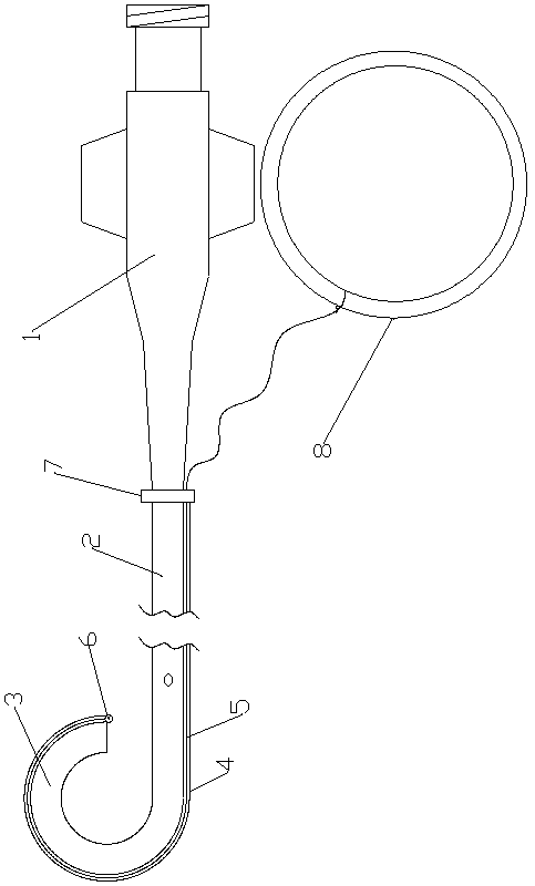
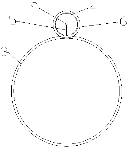
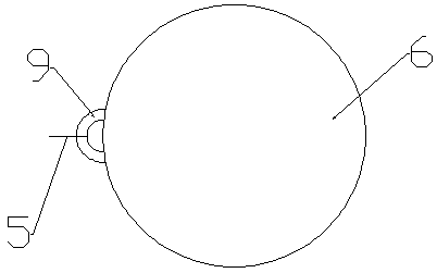
[0022] Such as figure 1 , 2 As shown in , 3 and 4, a contrast catheter with an adjustable end bending angle includes a joint 1, a catheter body 2 with a side hole at the end connected to the joint 1, and the outer end of the catheter body 2 A bent tube 3 which is integrated with the catheter body 2 is connected. The shape of the bent tube 3 is a three-quarter ring structure. The pull wire cavity 4 of integral structure, the pull wire cavity 4 extends around the outer side wall of the bent tube 3 to the connection position between the catheter body 2 and the joint 1, and a pull string 5 is arranged in the pull wire cavity 4, and one end of the pull string 5 is connected to the The bending limiter 6 outside the end of the bending tube 3 is connected, and the other end of the stay cord 5 is connected with the lifting limiter 8 arranged outside the end of the backguy cavity 4 near the joint 1 position.

[0023] The bending angle of the bending tube 3 is 270 degrees, the drawing ...


PUM


Abstract

The invention relates to an angiographic catheter with an adjustable end bending angle. The outer tail end of a catheter body is connected with a bent pipe which is of an integrated structure with thecatheter body, and the shape of the bent pipe is of a three-quarter annulus shaped structure; a stay wire chamber in an integrated structure with the bent pipe is formed at the center of the outer side wall of the bent pipe, and extends to the joint of the catheter body and a connector around the outer wall of the bent pipe; a stay cord is arranged in the stay wire chamber, one end of the stay cord is connected with a bending limit body which is arranged outside the end part of the bent pipe, and the other end of the stay cord is connected with a lifting limit body which is arranged outside the end part of the stay wire chamber and close to the connector. According to the angiographic catheter, the difficulty for leading a catheter into a branch vessel can be reduced; and by adopting a mode of payoff control, the operation time of a doctor implementing angiography in the angiography step can be saved, the X-ray radiation time on a patient can be reduced, entrance of a contrast agent can be accurately controlled, the quality of an angiography image can be improved, and final accurate diagnosis can be favored.

Description

technical field [0001] The invention relates to the medical field, in particular to a radiography catheter with an adjustable end bending angle. Background technique [0002] Catheter is an indispensable device for modern angiography. Its main function is to smoothly introduce contrast agent into blood vessels to produce contrast effects. Due to uncontrollable catheters and guide wires, the catheters and guide wires cannot reach the lesion as expected, which brings difficulties to the next step of interventional surgery. In addition, for some patients with atherosclerosis, the shape of the artery in a special part is usually very curved, so the head end of the existing angiography catheter is often difficult to stabilize at this part, so that the doctor who performs the angiography has to It takes a long time, and the X-ray radiation received by the patient has also increased significantly, but the part where the contrast agent enters the blood circulation is often still no...

Claims


Application Information

Patent Timeline
Patent Type & Authority Applications(China)
IPC IPC(8): A61M25/00A61M25/09
CPCA61M25/0074A61M25/008A61M25/09A61M2025/09116A61M2025/0079
Inventor 李宗明韩新巍焦德超马波吴正阳杨红周欢雷钦雨
Owner THE FIRST AFFILIATED HOSPITAL OF ZHENGZHOU UNIV
Learn More