Diesel oil and natural gas dual-fuel engine nozzle working method

A dual-fuel engine and working method technology, applied in combustion engines, internal combustion piston engines, engine components, etc., can solve the problems of poor atomization effect, high use cost, low reliability, etc., and achieve improved reactivity, improved combustion, Improve the effect of atomization

Active Publication Date: 2019-10-18
DALIAN NATIONALITIES UNIVERSITY
View PDF7 Cites 6 Cited by
  • Summary
  • Abstract
  • Description
  • Claims
  • Application Information

AI Technical Summary

Problems solved by technology

[0005] In order to solve the problems of poor atomization effect, high use cost and low reliability of existing engine dual-fuel nozzles, this application provides a working method for diesel and natural gas dual-fuel engine nozzles

Method used


Image

  • Diesel oil and natural gas dual-fuel engine nozzle working method
  • Diesel oil and natural gas dual-fuel engine nozzle working method
  • Diesel oil and natural gas dual-fuel engine nozzle working method

Examples


Embodiment 1

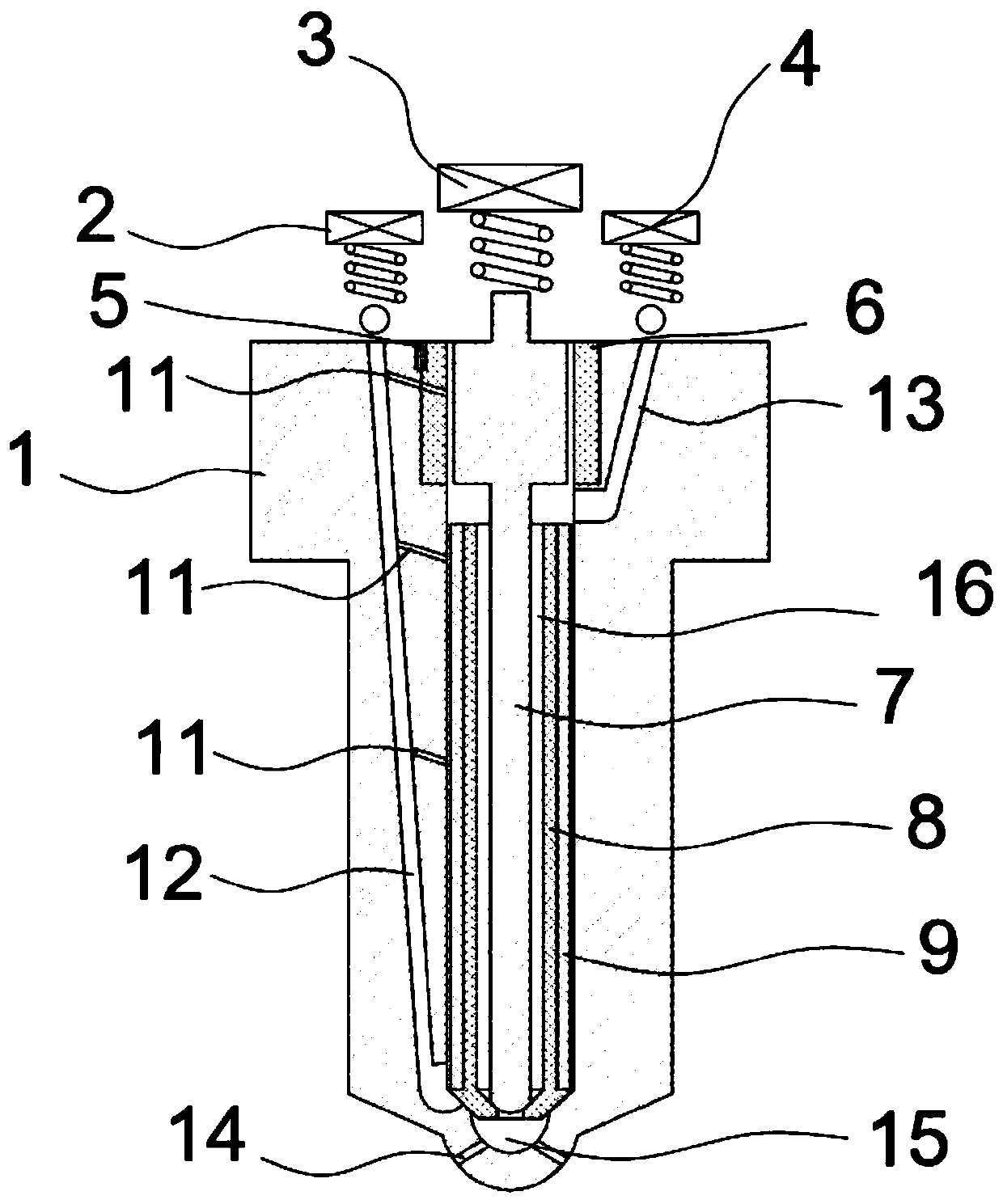
[0043] Such as Figure 1-3As shown, this embodiment provides a nozzle for a dual-fuel engine, including a nozzle body, a solenoid valve, a positioning pin, an insulating sleeve, a needle valve electrode, an insulating needle valve, and a grounding electrode; the nozzle body is the main structure and is used to carry other Each component and structure, and realize fuel injection, on described nozzle body, be processed with natural gas fuel channel 13, diesel fuel channel 12 and three lubricating holes 11; Described natural gas fuel channel 13 is used for introducing natural gas, and described diesel fuel channel For introducing diesel oil, the uppermost lubricating hole 11 is used to introduce a small amount of diesel oil from the diesel fuel passage 12 between the needle valve electrode 7 and the insulating sleeve 6, and the lower two lubricating holes are used to introduce a small amount of diesel oil from the diesel fuel passage 12. The channel is introduced between the oute...

Embodiment 2

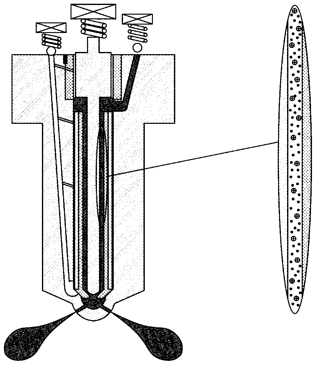
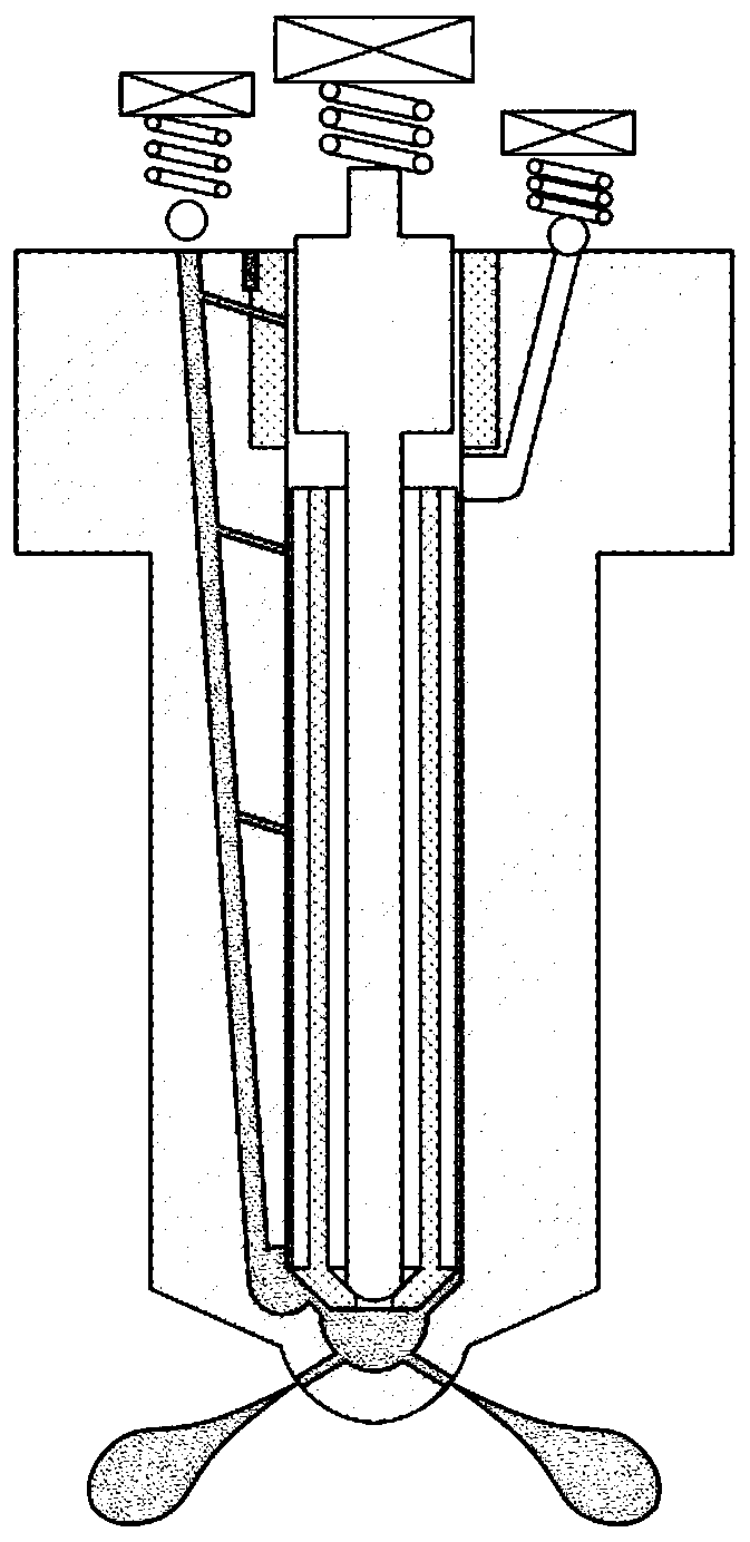
[0047] Such as Figure 4 As shown, the present embodiment provides a diesel and natural gas dual-fuel engine nozzle working method, the specific steps are:

[0048] (1) In the nth cycle, the crankshaft position sensor judges the crankshaft position. If the current crankshaft angle has not reached the set value, continue to judge; if it has reached the set value, the ECU outputs a lifting command to the solenoid valve b4. The time is recorded as the time origin t.

[0049] (2) The solenoid valve b4 is lifted, and the natural gas enters the natural gas fuel channel 13 through the fuel supply pipeline.

[0050] (3) Taking the time origin t as the starting point, after the calibrated Δt1 time interval (Δt1 is the time from the time origin t to the time when the natural gas is about to enter the ionization space 16), the ECU issues an instruction to power the needle valve electrode 7 Power supply with higher voltage U (for example: 15 ~ 20kV).

[0051] (4) Dielectric barrier dis...


PUM


Abstract

The invention discloses a diesel oil and natural gas dual-fuel engine nozzle working method. The diesel oil and natural gas dual-fuel engine nozzle working method specifically comprises the steps thatan electromagnetic valve b is firstly lifted, natural gas enters a natural gas fuel passage, then a needle valve electrode discharges electricity, the natural gas in an ionization space forms plasmasunder the electric field action, at the time, the needle valve electrode is lifted, and the ionized high-activity natural gas is sprayed into an engine combustion chamber through an injection hole; and then natural gas supply is stopped, diesel oil supply is started, a small amount of diesel oil is injected into the combustion chamber through a diesel oil fuel passage, a pressure chamber and an injection hole, a fire is caught under the action of the huge pressure temperature in an engine cylinder, and the natural gas sprayed into the combustion chamber at the time is ignited. As the naturalgas is ionized into the high-reactivity plasmas which are easily ignited by the diesel oil, combustion is started.

Description

technical field [0001] The invention relates to a nozzle working method, in particular to a diesel and natural gas dual fuel engine nozzle working method. Background technique [0002] The increasingly stringent energy-saving and environmental protection requirements have become the biggest challenge in the field of engine research. With the continuous innovation of engine technology, under different loads and different working conditions, the fuel requirements for the best economy, power and emission characteristics of the engine are also very different. Therefore, traditional single-fuel engines have gradually failed to meet people's requirements in some specific applications. Under this trend, dual-fuel engines have become an inevitable choice. [0003] Since the injection strategies of different fuels can be flexibly controlled according to specific working conditions to achieve good engine performance, dual-fuel engines have been gradually applied to power fields such...

Claims


Application Information

Patent Timeline
Patent Type & Authority Applications(China)
IPC IPC(8): F02M43/04F02M61/10F02M61/18F02M27/04F02D41/30F02M63/00F02M51/06
CPCF02D41/30F02M27/042F02M43/04F02M51/061F02M61/10F02M61/18F02M63/0017Y02T10/12
Inventor 宋鹏
Owner DALIAN NATIONALITIES UNIVERSITY
Why Eureka
Try Eureka