Wiring structure of electric control oil atomizer
A technology of electronically controlled fuel injection and wiring structure, which is applied to machines/engines, fuel injection devices, and engine sealing devices, etc. Simple and compact effect
- Summary
- Abstract
- Description
- Claims
- Application Information
AI Technical Summary
Problems solved by technology
Method used
Image

Examples
Embodiment 1
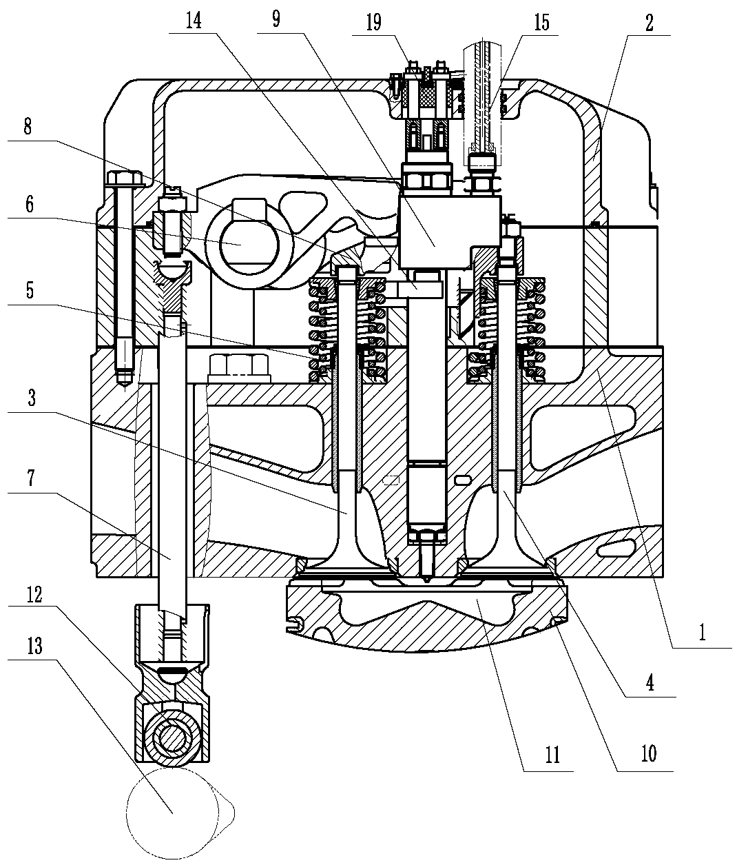
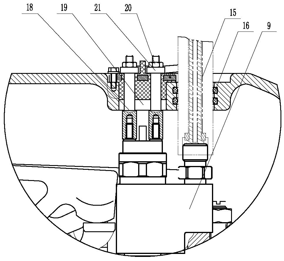
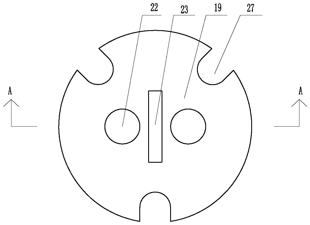
[0020] Embodiment 1: Two through-holes 22 that cooperate with the connecting studs 18 are opened on the sealing member 19, and a partition 23 located between the two through-holes 22 is installed on the upper surface of the sealing member 19; the connecting stud 18 includes a lower internal thread Connecting part 18-1, middle polished rod part 18-2, upper external thread connecting part 18-3, solenoid valve connecting post 17 are threadedly connected with lower internal thread connecting part 18-1, and the size of lower internal thread connecting part 18-1 is larger than that of through The inner diameter of the hole 22, the size of the upper external thread connection part 18-3 is smaller than the internal diameter of the through hole 88 and is exposed to the seal 19, and the upper external thread connection part 18-3 is equipped with a coupling piece 21 and a locking nut 20; the through hole The inner wall of 22 is a plane, and the outer surface of the middle polished rod por...
Embodiment 2
[0021] Embodiment 2: Two through-holes 22 cooperating with the connecting studs 18 are opened on the sealing member 19, and a partition 23 located between the two through-holes 22 is installed on the upper surface of the sealing member 19; the connecting stud 18 includes a lower internal thread Connecting part 18-1, middle polished rod part 18-2, upper external thread connecting part 18-3, solenoid valve connecting post 17 are threadedly connected with lower internal thread connecting part 18-1, and the size of lower internal thread connecting part 18-1 is larger than that of through The inner diameter of the hole 22, the size of the upper external thread connection part 18-3 is smaller than the internal diameter of the through hole 88 and is exposed to the seal 19, and the upper external thread connection part 18-3 is equipped with a coupling piece 21 and a locking nut 20; the through hole The inner wall of 22 is provided with an inner sealing ring 25, and the inner diameter o...
PUM
 Abstract
Description
Claims
Application Information