Telescope pointing error correction method and telescope

A pointing error and correction method technology, applied in the field of telescopes, can solve problems such as the inability to accurately correct telescope pointing errors, achieve the effects of improving system pointing accuracy, eliminating alignment deviation, and reducing system aberrations

Active Publication Date: 2019-10-22
CHANGCHUN INST OF OPTICS FINE MECHANICS & PHYSICS CHINESE ACAD OF SCI
View PDF7 Cites 12 Cited by
  • Summary
  • Abstract
  • Description
  • Claims
  • Application Information

AI Technical Summary

Problems solved by technology

[0008] In view of this, in order to solve the problem that the telescope pointing error cannot be accurately corrected in the prior art, the present invention provides a method for correcting the telescope pointing error, which is applied to the telescope, and the telescope includes a primary mirror, a secondary mirror, a tracking frame and The main control unit, the tracking frame includes an azimuth axis assembly and a pitch axis assembly, and the position and speed control of the azimuth axis assembly and the pitch axis assembly are realized by the rack spindle servo control system, and the main mirror The secondary mirror is connected to the tracking frame, the bottom surface and the side of the primary mirror are provided with several position sensors, the secondary mirror is supported by a six-degree-of-freedom platform, and the position sensor and the six-freedom The degree platform is controlled by the main control unit;

Method used


Image

  • Telescope pointing error correction method and telescope
  • Telescope pointing error correction method and telescope
  • Telescope pointing error correction method and telescope

Examples


Embodiment 1

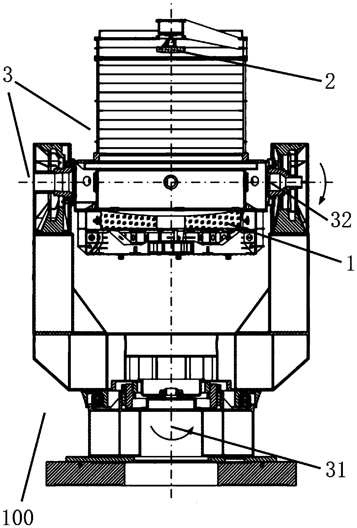
[0043] An embodiment of the present invention provides a telescope pointing error correction method, which is applied to the telescope 100, figure 1 It is a schematic structural diagram of a telescope according to an embodiment of the present invention. The telescope 100 includes a main mirror assembly 1, a secondary mirror assembly 2, a main control unit, and a tracking frame 3, and the tracking frame 3 includes an azimuth axis system assembly 31 and a pitch axis system assembly 32. The position and speed control of the azimuth axis system component 31 and the pitch axis system component 32 is realized by the gantry spindle servo control system 4. The main control unit is used to execute the control steps in the calibration process.

[0044] The main mirror assembly 1 includes a main mirror 11, and the main mirror 11 adopts a passive support structure. Several position sensors are respectively provided on the bottom surface and the side surface of the main mirror 11 to identify...


PUM


Abstract

The invention provides a telescope pointing error correction method comprising the concrete steps: a master control unit obtains the data measured by a position sensor, calculating the first deviationbetween the current optical axis position of a primary mirror and the ideal optical axis position and outputting the first deviation to a frame spindle servo control system to make the frame spindleservo control system perform correction; and the master control unit obtains the attitude of the telescope, calculates the current optical axis position of a secondary mirror, then calculates the second deviation of the current position of the secondary mirror according to the current optical axis position of the primary mirror and the calculated current optical axis position of the secondary mirror and outputs the second deviation to a six-degree-of-freedom platform to enable the six-degree-of-freedom platform to perform correction. The invention also provides a telescope. Compared with the methods in the prior art, the beneficial effects are that the correction method can correct the pointing error caused by the spindle jitter of the telescope due to the external interference and can also correct the pointing error caused by the alignment of the primary and secondary mirrors so as to improve the optical performance of the telescope.

Description

Technical field [0001] The invention relates to the imaging detection field of a photoelectric telescope, in particular to a method for correcting the pointing error of a telescope and a telescope. Background technique [0002] With the continuous increase in space activities of various countries, more than 42,000 targets have been sent into space, and about 50% are still left in space and fly along orbit, but only about 1,200 of them are working spacecraft, and the rest are space debris. Space debris has become an important factor threatening the safety of orbiting spacecraft. Space debris will not only collide with the spacecraft and destroy the spacecraft, it will also cause the waste of orbital resources and the interruption of space networks. In order to safely and continuously develop and utilize space resources, it is necessary to vigorously develop high-precision tracking and monitoring technology for space debris. In the field of high-precision space tracking and monitor...

Claims


Application Information

Patent Timeline
Patent Type & Authority Applications(China)
IPC IPC(8): G02B7/183G01M11/02G02B23/02
CPCG02B7/183G01M11/02G02B23/02
Inventor 曹玉岩王建立李洪文韩西达王志臣赵勇志
Owner CHANGCHUN INST OF OPTICS FINE MECHANICS & PHYSICS CHINESE ACAD OF SCI
Why Eureka
Try Eureka