Gridding ultrasonic tomography detection method for defects of shaft workpieces

A technology of ultrasonic tomography and shaft workpieces, which is applied in the direction of material analysis, material analysis, and image enhancement using sound waves/ultrasonic waves/infrasonic waves. To solve problems such as high labor intensity of inspectors, achieve effective detection and positioning imaging, easy to learn operation methods, and improve sensitivity and effectiveness

Active Publication Date: 2019-10-22
CHINA SPECIAL EQUIP INSPECTION & RES INST
View PDF11 Cites 12 Cited by
  • Summary
  • Abstract
  • Description
  • Claims
  • Application Information

AI Technical Summary

Problems solved by technology

[0003] However, the traditional ultrasonic testing of shafts mostly adopts the method of radial detection and continuous scanning along the circumference. The assumption of straight radiation from the axis of the probe, however, in actual testing, the beam radiated by the ultrasonic wave source is not radiated straight from the wave source, but diffused outwards at a certain angle, so the above assumptions lead to the processing of the obtained echo data fundamentally. It is impossible to accurately reflect the defect on the
In addition, the traditional imaging of defect detection is displayed through A, B, C, and D scans, which cannot traverse and present the detection situation of each detection surface to intuitively judge the defect position and range

Method used


Image

  • Gridding ultrasonic tomography detection method for defects of shaft workpieces
  • Gridding ultrasonic tomography detection method for defects of shaft workpieces
  • Gridding ultrasonic tomography detection method for defects of shaft workpieces

Examples


Embodiment Construction

[0040] Specific embodiments of the present invention will be described below in conjunction with the accompanying drawings, so as to clearly understand the purpose, technical solutions and advantages of the present invention.

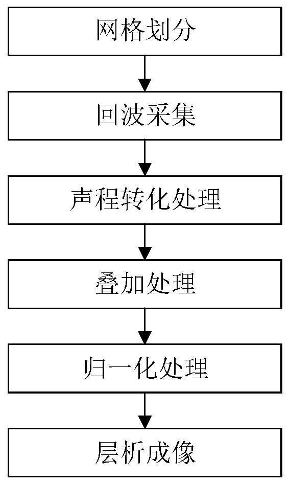
[0041] The grid-drawing ultrasonic tomography detection method for shaft workpiece defects according to the present invention comprises the following steps, and the block diagram of the method steps can be found in figure 1 :

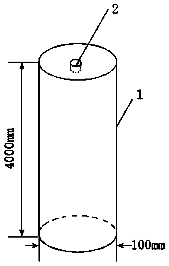
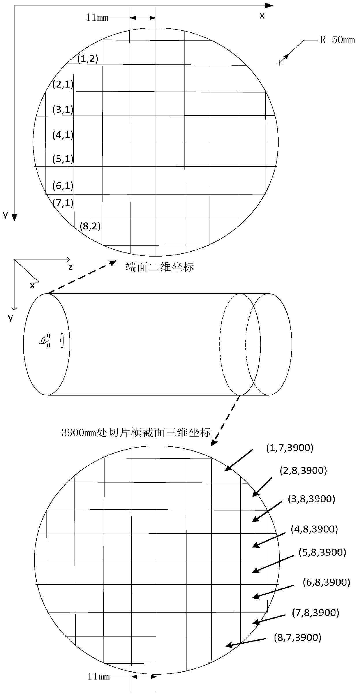
[0042] Step 1, grid division: According to the diameter D of the ultrasonic longitudinal wave straight probe and the size of the end surface of the shaft workpiece to be measured, a square grid is divided on the end surface of the shaft workpiece, and each grid corresponds to a sampling point.

[0043] figure 2 It is a schematic diagram of the structure of the shaft workpiece to be measured, 1 represents the shaft type workpiece to be measured; 2 represents the ultrasonic longitudinal wave straight probe, and the length of the ...


PUM


Abstract

The invention discloses a gridding ultrasonic tomography detection method for defects of shaft workpieces. The method comprises the following steps: meshing an end surface area at one end of a workpiece; adopting a grid center as an ultrasonic probe sampling point, adopting an ultrasonic pulse echo method is used for sequentially collecting time domain signals of all sampling points and then converting the time domain signals into spatial depth signals, echo amplitudes corresponding to all depths are obtained, the position where defect echoes are located is clearly located, and detection of internal defects of shaft workpieces is achieved. According to the invention, acoustic beam diffusivity is also considered; superposing all reflection signal amplitudes which can be diffused to a certain position; echo amplitudes of cross sections at different depths in the workpiece are reconstructed by adopting amplitude data after superposition processing, and information of the cross sections inthe workpiece is displayed by tomography, so that the depth and two-dimensional distribution of defects are effectively identified, and the defect detection rate is greatly improved. According to themethod, a complex scanning array does not need to be arranged, comprehensive, visual and effective detection and positioning imaging of the internal defects of the shaft workpiece are achieved. The detection operation difficulty is reduced, and the operation efficiency, the detection rate and the reliability of a detection result are improved.

Description

technical field [0001] The invention relates to the technical field of ultrasonic non-destructive testing, in particular to a gridded ultrasonic tomographic detection method for shaft workpiece defects. Background technique [0002] Shaft workpieces are one of the most commonly used parts and vulnerable parts in various mechanical equipment. Defects in shaft workpieces will cause a series of problems such as severe vibration and noise of the machine, and even cause damage to the equipment. Ultrasonic testing has strong penetrating power, high sensitivity, low cost, and fast speed. It can detect large steel forgings up to several meters long. Therefore, ultrasonic nondestructive testing methods are suitable for testing shaft workpieces. [0003] However, the traditional ultrasonic testing of shafts mostly adopts the method of radial detection and continuous scanning along the circumference. The assumption of straight radiation from the axis of the probe, however, in actual t...

Claims


Application Information

Patent Timeline
Patent Type & Authority Applications(China)
IPC IPC(8): G06T7/00G06T7/70G01N29/44
CPCG01N29/4454G01N2291/023G06T7/0004G06T2207/10132G06T7/70
Inventor 胡斌张琪原可义
Owner CHINA SPECIAL EQUIP INSPECTION & RES INST
Why Eureka
Try Eureka