D type photonic crystal fiber refractive index sensor using double-loss-peak detection

A technology of photonic crystal fiber and refractive index sensor, which is applied in the direction of cladding fiber, optical waveguide light guide, optics, etc., can solve the problem of low single-peak detection accuracy and recognition, loss peak detection spectral range is not optional, and detection methods are not perfect, etc. problems, to achieve the effect of good operation convenience, accurate and efficient detection means

Active Publication Date: 2019-10-25
河北鹏博通信设备有限公司
View PDF9 Cites 9 Cited by
  • Summary
  • Abstract
  • Description
  • Claims
  • Application Information

AI Technical Summary

Problems solved by technology

[0006] It should be pointed out that the current SPR fiber optic sensors are b...

Method used


Image

  • D type photonic crystal fiber refractive index sensor using double-loss-peak detection
  • D type photonic crystal fiber refractive index sensor using double-loss-peak detection
  • D type photonic crystal fiber refractive index sensor using double-loss-peak detection

Examples


Embodiment 1

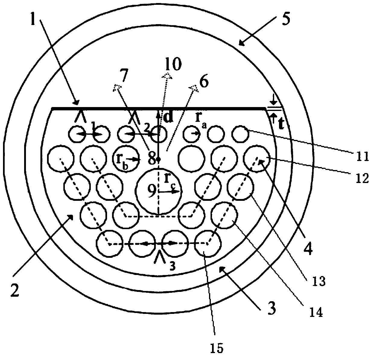
[0057] figure 1 It is the end face structure diagram of the D-type photonic crystal fiber refractive index sensor capable of double loss peak detection according to the present invention. exist figure 1 In the process, a layer of gold film 1 is deposited on the polished surface of the optical fiber. The thickness of the gold film is 40nm, which is used as the induction material for the surface plasmon resonance effect; next to the gold film is the liquid analyte 3, and the sensor is used It is enough to completely immerse the optical fiber in the liquid 3 of the analyte to be measured; the outermost layer is the perfect matching layer 5, which is the calculation boundary and auxiliary settings added when performing performance simulation by using the finite element method.

[0058] The base material 2 of the optical fiber is quartz; many air holes of different sizes are set in the quartz material, and the existence of air holes in the cladding reduces the effective refractive...

Embodiment 2

[0074] The structural parameters of the sensor in this embodiment are exactly the same as those in the first embodiment, and its characteristic description and performance characterization are also exactly the same as those in the first embodiment. This embodiment will specifically illustrate and further illustrate various usages of the invented sensor.

[0075] Figure 9 Shown is the schematic diagram of the specific operation and use instructions of the present invention. First, the two ends of the D-type photonic crystal fiber refractive index sensor described in the present invention are respectively fused with a single-mode fiber to form a sensor 102; then, one end of the sensor 102 is connected to a broadband light source 100 through a coupling device 101, and the other end of the sensor 102 is connected to the sensor 102. The inlet end of the beam splitter 103 is fused, and the two beams of light coming out of the beam splitter are respectively connected to a spectrome...


PUM

PropertyMeasurementUnit
Thicknessaaaaaaaaaa

Abstract

The invention discloses a D type photonic crystal fiber refractive index sensor using double-loss-peak detection. The sensor comprises a base material, cladding air holes, a metal film, to-be-detectedanalyte liquid and a perfectly matching layer. The base material is made of a quartz material. The cladding air holes include 25 air holes arranged vertically in parallel in five layers and one largeair hole arranged below the center of the fiber. According to the invention, a gold film is deposited on a polished surface of the D type fiber and is used as an inducing material for surface plasmonresonance effect generation. A liquid analyte is arranged at the outermost layer. When the sensor is used, the fiber is required to be immersed into the to-be-detected analyte liquid completely. According to the specific embodiment, the sensor not only can use two loss peaks to detect the to-be-detected analyte but also can select different types of spectrum detectors flexibly based on specific experimental conditions and application requirements or select one single peak randomly from the two loss peaks for detection.

Description

technical field [0001] The invention relates to the field of optical fiber sensing, in particular to a D-type photonic crystal optical fiber refractive index sensor using double loss peak detection. Background technique [0002] When light is transmitted in the fiber, some light will leak from the core to the cladding, resulting in loss of light transmitted in the core. When certain conditions are met, there will be a directional coupling effect between the optical modes transmitted by the core and cause There are obvious loss peaks at certain wavelengths, and this phenomenon can be used to make optical fibers into photonic devices such as optical filters, beam splitters or sensors. However, when the loss peak generated by this directional coupling effect is used for optical fiber sensing and detection, it is generally possible to detect the high refractive index region, and the sensing sensitivity is low, and it is more difficult to form an effective loss peak phenomenon in...

Claims


Application Information

Patent Timeline
IPC IPC(8): G01N21/41G02B6/02
CPCG01N21/41G02B6/02304
Inventor 李建设孟潇剑李曙光郭英卢辉斌程同蕾张树桓
Owner 河北鹏博通信设备有限公司
Why Eureka
Try Eureka