Deep Trench Isolation Process

A process method, deep groove technology, applied in the manufacturing of electrical components, circuits, semiconductor/solid-state devices, etc., to reduce challenges, reduce difficulty, and save masks

Active Publication Date: 2022-01-14
SHANGHAI HUAHONG GRACE SEMICON MFG CORP
View PDF3 Cites 0 Cited by
  • Summary
  • Abstract
  • Description
  • Claims
  • Application Information

AI Technical Summary

Problems solved by technology

The traditional process has great challenges for dry etching and subsequent trench filling

Method used


Image

  • Deep Trench Isolation Process
  • Deep Trench Isolation Process
  • Deep Trench Isolation Process

Examples


Embodiment Construction

[0032] The deep trench isolation process method described in the present invention is described as follows in conjunction with the accompanying drawings, and each step corresponds to Figure 1 to Figure 10 , including the following process steps:

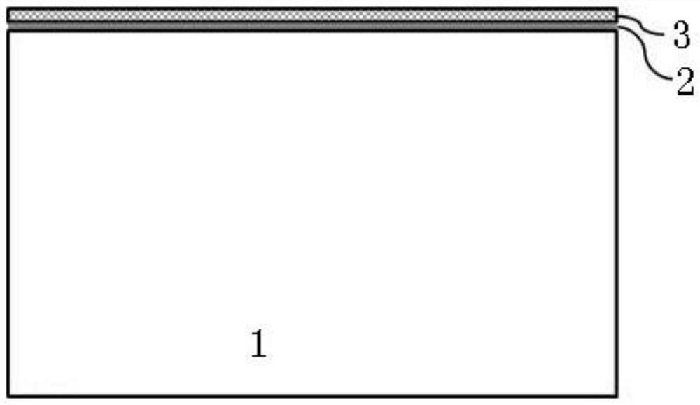
[0033] In step 1, a semiconductor substrate is provided, and a silicon oxide layer and a silicon nitride layer are sequentially formed on the surface of the semiconductor substrate, such as figure 1 shown. Forming the silicon oxide layer and the silicon nitride layer adopts a traditional deposition process to form a film layer with uniform thickness and good quality on the surface of the semiconductor substrate.

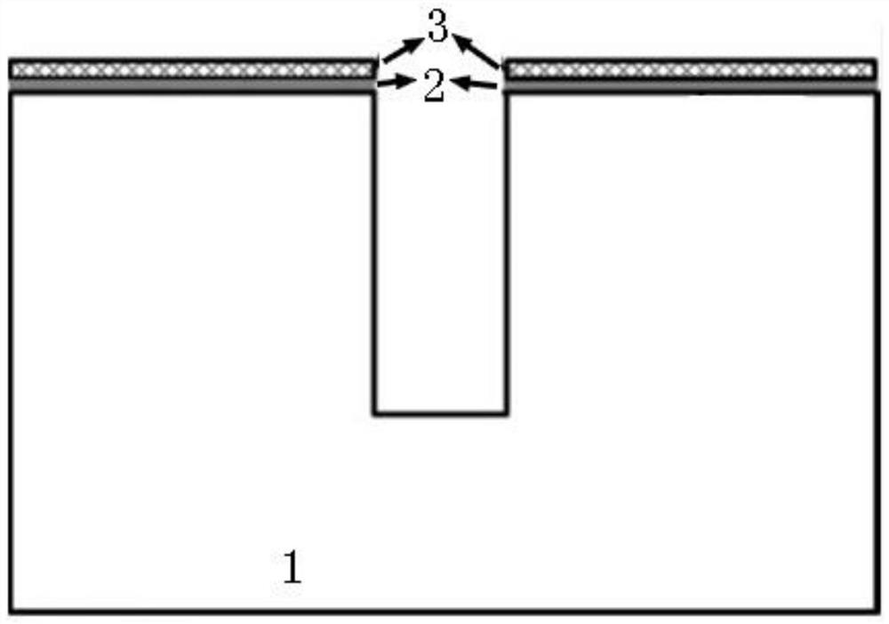
[0034] Step 2: Etch the silicon nitride layer and the silicon oxide layer through the definition of photoresist, open the area where the deep trench is to be formed, etch downward to form a trench with a certain depth, and the depth of the downward etching can be freely It is determined that the downward etching depth i...


PUM


Abstract

The invention discloses a deep trench isolation process method, comprising: sequentially forming a silicon oxide layer and a silicon nitride layer on the surface of a semiconductor substrate; defining the silicon nitride layer and the silicon oxide layer through photoresist definition Etching, opening the area where a deep trench is to be formed, and etching down to form a trench of a certain depth; forming a pad oxide layer in the trench, and then filling polysilicon; etching back polysilicon; performing furnace tube oxidation to form a silicon oxide layer; Removing the silicon oxide layer and silicon nitride layer; performing epitaxial growth; forming a silicon oxide layer, and then filling polysilicon; etching back the polysilicon on the epitaxial surface and the polysilicon in the deep trench; etching and removing the silicon oxide layer on the epitaxial surface. The process method of the present invention forms a part-depth trench before the epitaxial deposition process, and then utilizes the selective growth characteristics of the epitaxial deposition process to form subsequent trenches, which reduces the difficulty of dry etching and reduces the depth of the trench. The challenge of slot filling can save a zero-layer mask.

Description

technical field [0001] The invention relates to the field of semiconductor device manufacturing, in particular to a deep trench isolation process method for nodes below the 0.18 μm BCD process. Background technique [0002] Trench filling is a particularly critical step in semiconductor manufacturing. At present, silicon dioxide and its derivatives are widely used in trench filling due to their good film properties. Traditional preparation techniques include spin coating (Spin on Glass), sub-atmospheric pressure chemical vapor deposition (SACVD: Sub Atmosphere Chemical Vapor Deposition), plasma chemical vapor deposition (PECVD: Plasma Enhanced Chemical Vapor Deposition) and high-density plasma chemical vapor deposition. Vapor deposition method (HDPCVD: High Density Plasma Chemical Vapor Deposition), etc. The usual trench structure has a depth of no more than 1 micron and an opening of less than 0.25 micron (the size of the opening is fixed). Such a structure can be filled ...

Claims


Application Information

Patent Timeline
Patent Type & Authority Patents(China)
IPC IPC(8): H01L21/762
CPCH01L21/76224
Inventor 王星杰
Owner SHANGHAI HUAHONG GRACE SEMICON MFG CORP
Why Eureka
Try Eureka