
Light-emitting diode epitaxial wafer and growth method thereof

A technology of light-emitting diodes and epitaxial wafers, applied in semiconductor devices, electrical components, circuits, etc., can solve problems such as lattice mismatch, poor crystal quality of the P-type GaP window layer, and reduce LED luminous efficiency, etc. Mismatch, the effect of improving luminous efficiency

Active Publication Date: 2020-11-17
HC SEMITEK SUZHOU
View PDF14 Cites 0 Cited by
  • Summary
  • Abstract
  • Description
  • Claims
  • Application Information

AI Technical Summary

Problems solved by technology

[0005] There is a lattice mismatch between the P-type GaP window layer and the P-type AlInP confinement layer, and the stress and defects caused by the lattice mismatch cause the crystal quality of the P-type GaP window layer to deteriorate
The deterioration of the crystal quality of the P-type GaP window layer leads to a decrease in the light transmittance of the P-type GaP window layer. The P-type GaP window layer located on the light-emitting side of the chip will affect the light emitted from the active layer by radiative recombination and reduce the light emission of the LED. efficiency

Method used


Image

  • Light-emitting diode epitaxial wafer and growth method thereof
  • Light-emitting diode epitaxial wafer and growth method thereof
  • Light-emitting diode epitaxial wafer and growth method thereof

Examples


Embodiment Construction

[0026] In order to make the object, technical solution and advantages of the present invention clearer, the implementation manner of the present invention will be further described in detail below in conjunction with the accompanying drawings.

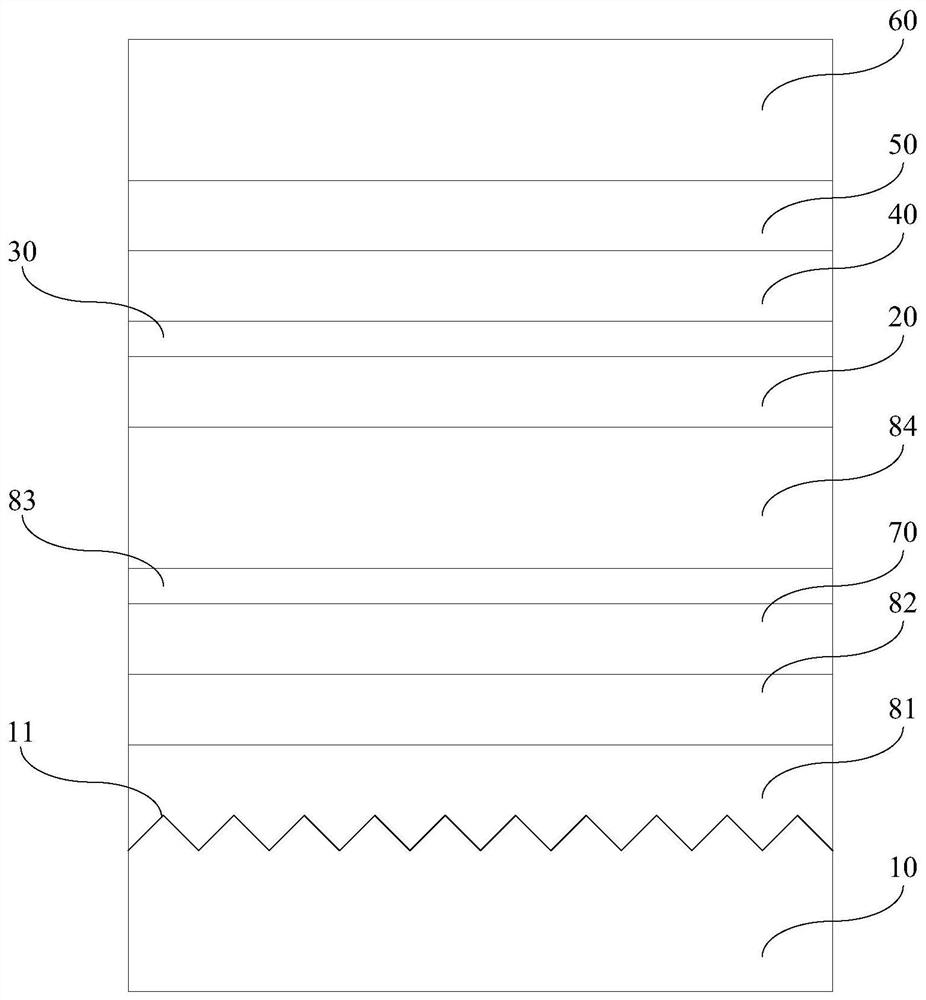
[0027] An embodiment of the present invention provides a light emitting diode epitaxial wafer. figure 1 A schematic structural diagram of a light emitting diode epitaxial wafer provided by an embodiment of the present invention. see figure 1 , the light-emitting diode epitaxial wafer comprises a substrate 10, an N-type confinement layer 20, an active layer 30, a P-type AlInP confinement layer 40, a transition layer 50 and a P-type GaP window layer 60, an N-type confinement layer 20, an active layer 30 , a P-type AlInP confinement layer 40 , a transition layer 50 and a P-type GaP window layer 60 are sequentially stacked on the substrate 10 .

[0028] figure 2 Schematic diagram of the structure of the transition layer provided by the...


PUM

PropertyMeasurementUnit
thicknessaaaaaaaaaa
diameteraaaaaaaaaa
diameteraaaaaaaaaa

Abstract

The invention discloses a light emitting diode epitaxial wafer and a growth method thereof, and belongs to the technical field of semiconductors. The epitaxial wafer comprises a substrate, an N-type limiting layer, an active layer, a P-type AlInP limiting layer, a transition layer and a P-type GaP window layer, which are stacked in sequence. The transition layer comprises (N+1) first sub-layers and N second sub-layers, which are alternately stacked; each first sub-layer is an AlGaInP layer; the content of the Al component in the (N+1) first sub-layers is gradually decreased in the direction from the P-type AlInP limiting layer to the P-type GaP window layer, and the content of the Ga component in the (N+1) first sub-layers is gradually increased in the direction from the P-type AlInP limiting layer to the P-type GaP window layer; each second sub-layer is a GaP layer, and the total thickness of the N second sub-layers is 1 / 200-1 / 20 of the total thickness of the (N+1) first sub-layers. The light-emitting efficiency of an LED can be improved.

Description

technical field [0001] The invention relates to the technical field of semiconductors, in particular to a light-emitting diode epitaxial wafer and a growth method thereof. Background technique [0002] Light Emitting Diode (English: Light Emitting Diode, referred to as: LED) is a semiconductor diode that can convert electrical energy into light energy, and has been widely used in display, decoration, communication and other fields. By using different semiconductor materials, the luminous wavelength of the LED can cover the full-color range from ultraviolet to infrared, and the luminous efficiency and luminous brightness of the LED are continuously improved. [0003] The chip is the core component of the LED, including epitaxial wafers and N-type electrodes and P-type electrodes respectively arranged on the epitaxial wafers. For red and yellow LED chips, the LED epitaxial wafer includes GaAs substrate, N-type AlInP confinement layer, AlGaInP active layer, P-type AlInP confin...

Claims


Application Information

Patent Timeline
Patent Type & Authority Patents(China)
IPC IPC(8): H01L33/12H01L33/30H01L33/00
CPCH01L33/0062H01L33/12H01L33/30
Inventor 兰叶陶羽宇常远吴志浩
Owner HC SEMITEK SUZHOU
Learn More