
Transformer oil heating device and method for large fire test

A transformer oil and heating device technology, which is applied in the testing of measuring devices, instruments, machines/structural components, etc., can solve the problems of slow heating rate, high oil temperature, easy accidental ignition of transformer oil, etc., and achieve fast speed and heating The effect of high temperature

Active Publication Date: 2019-10-29
应急管理部天津消防研究所 +2
View PDF5 Cites 11 Cited by
  • Summary
  • Abstract
  • Description
  • Claims
  • Application Information

AI Technical Summary

Problems solved by technology

However, the existing conventional oil-immersed transformer physical fire test usually uses normal temperature transformer oil, without considering the problem of transformer oil heating, and because the large-scale oil-immersed transformer physical fire test involves a large amount of oil, high oil temperature, and complicated working conditions, there are great risks. Inflammable and explosive risks, conventional gas heating devices, oil filter units, electric heating and other heating devices and methods cannot meet the demand
Specifically: (1) Conventional gas heating devices involve open flames. When the oil temperature exceeds the ignition point, the transformer oil may be accidentally ignited, resulting in failure to reach the expected oil temperature, or failing to follow the predetermined test plan, posing a major safety hazard.
(2) The maximum oil temperature of the conventional oil filter unit is limited, and the heating rate is slow, which cannot meet the requirements of the physical fire test of large oil-immersed transformers

Method used


Image

  • Transformer oil heating device and method for large fire test
  • Transformer oil heating device and method for large fire test
  • Transformer oil heating device and method for large fire test

Examples


Embodiment 1

[0017] The hot oil pump adopts LQRY100 single-stage high-temperature heat-conducting oil pump.

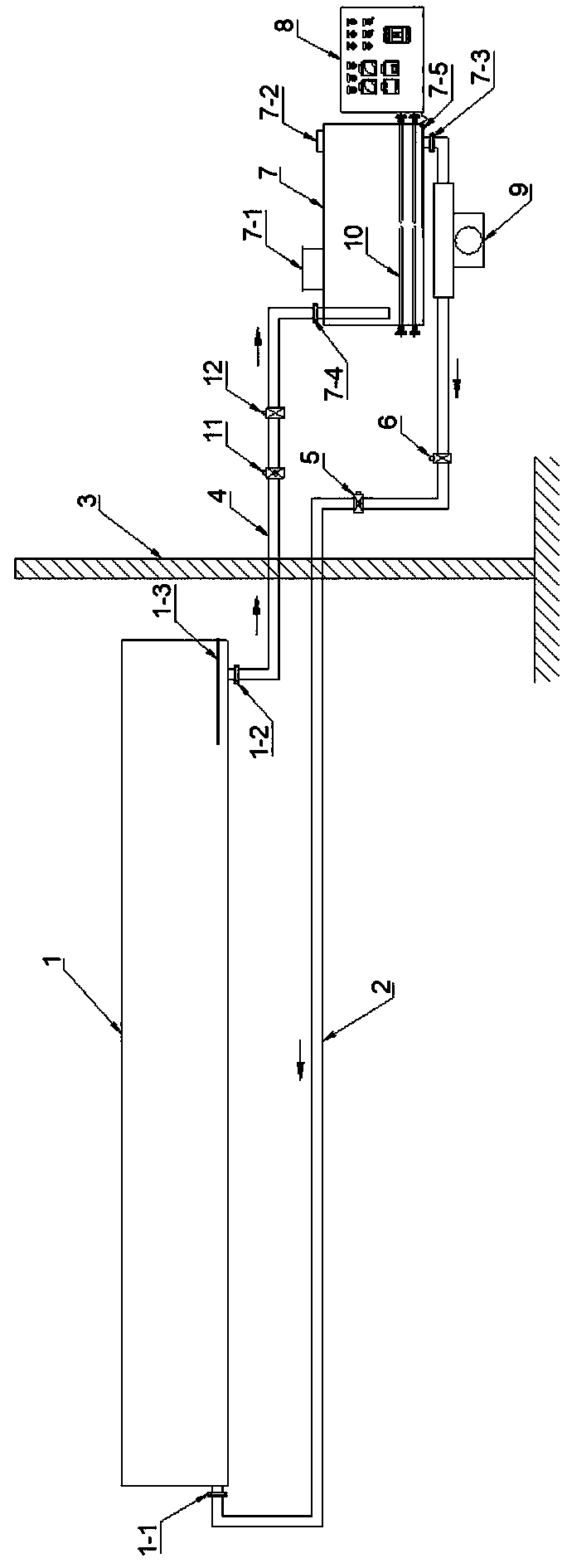
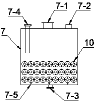
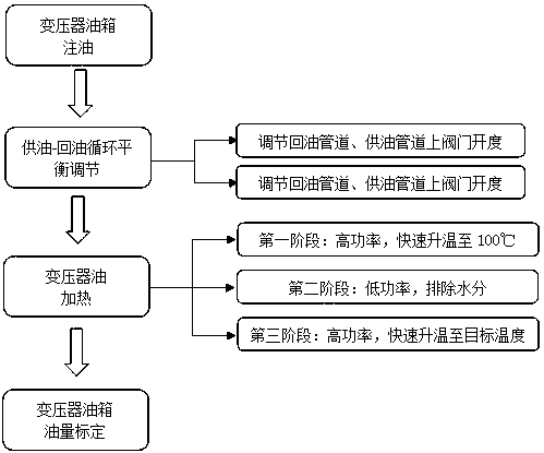
[0018] The lower part of the heating tank is evenly equipped with three sets of electric heating tubes. Each set of electric heating tubes contains twelve electric heating tubes. The electric heating tubes use EH-15 type heating rods. , the heating tank control cabinet contains three on-off switches, which are heated by the two-stage three-stage heating method as shown in Table 1. Each on-off switch controls a group of electric heating tubes, and by turning on 1 group, 2 groups or 3 groups of electric heating Tubes, so as to achieve three different heating powers, and can also use a single electric heating tube with different powers to achieve more different heating powers.

[0019] Table 1 Two-stage three-stage heating method

[0020] stage Heating power / kW Target temperature / ℃ Remark The first stage 540 100 High power heating, rapid heating second s...


PUM


Abstract

The invention relates to a transformer oil heating device and method for a large fire test. The transformer oil heating device comprises a transformer oil tank, an oil supply pipeline, a fire separation wall, a return oil pipeline, an electric valve, a manual valve, a heating tank, an electric control system, an hot oil pump, and an electric heating tube, wherein the transformer oil tank is filledwith transformer oil and has an open top or a combustion port on the top; the fire separation wall is arranged between the transformer oil tank and the heating tank to prevent the heating tank from burning and exploding when the transformer fuel tank is burned and to adjust the oil supply-oil return circulation balance. After the transformer oil is electrically heated to the predetermined temperature in steps and in stages, the heating system is stopped and the transformer oil tank has a predetermined oil level. The transformer oil heating device has high heating temperature, high speed, excellent safety and reliability, good repeatability, provides powerful technical support for a large oil-immersed transformer fire test, can be used for the study of fire characteristics of large oil-immersed transformers, as well as for the evaluation of large oil-immersed transformer fire-fighting technology.

Description

technical field [0001] The invention relates to the field of large-scale oil-immersed transformer solid fire tests, in particular to a transformer oil heating device and heating method for large-scale solid fire tests. Background technique [0002] In recent years, with the rapid development of my country's economy and society, a number of high-voltage, ultra-high and ultra-high power transmission projects and tens of thousands of large oil-immersed transformers above 220kV have emerged. When a large number of large oil-immersed transformers are put into use, their fire prevention and control technology is far behind the actual needs. Large-scale oil-immersed transformers have large volume, large oil storage capacity, and high operating temperature. Large-scale oil-immersed transformers above 220kV have an oil storage capacity of 50t-130t, especially the oil tank of UHV converter transformers. It is far more than conventional oil-immersed transformers, and the operating tem...

Claims


Application Information

Patent Timeline
IPC IPC(8): G01M99/00
CPCG01M99/002
Inventor 陈涛胡成赵力增傅学成李宝利包志明洪清泉张佳庆
Owner 应急管理部天津消防研究所
Learn More