
Method for anti-bending reinforcement of beam end with floor

A technology of floor slabs and admixtures, applied in building maintenance, construction, building construction, etc., can solve the problems of reduced reliability of reinforcement, easy aging of structural adhesives, complicated actual operation, etc., to achieve reduced thickness, easy anchorage and lap joint positioning , the effect of easy construction

Pending Publication Date: 2019-11-01
HUNAN UNIV OF TECH
View PDF5 Cites 1 Cited by
  • Summary
  • Abstract
  • Description
  • Claims
  • Application Information

AI Technical Summary

Problems solved by technology

[0005] Most of the traditional beam bending reinforcement methods use carbon fiber cloth, carbon fiber plate, steel plate or steel mesh for reinforcement. This method needs to level the surface of the original structural concrete and paste the structural adhesive, because the structural adhesive is easy to aging and not resistant to high temperature , the reliability of reinforcement is greatly reduced, and the actual operation is more complicated

Method used


Image

  • Method for anti-bending reinforcement of beam end with floor
  • Method for anti-bending reinforcement of beam end with floor
  • Method for anti-bending reinforcement of beam end with floor

Examples


Embodiment Construction

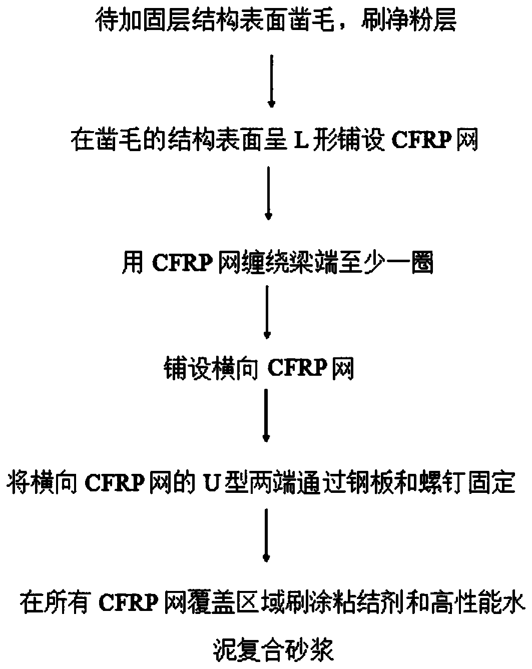
[0033] The present invention will be further described below in conjunction with the accompanying drawings and specific embodiments. The accompanying drawings are for illustrative purposes only, and should not be construed as limitations on the invention; in order to better illustrate this embodiment, certain components in the accompanying drawings will be omitted, enlarged or reduced, and do not represent the size of the actual product; for those skilled in the art It is understandable that some well-known structures and descriptions thereof may be omitted in the drawings. The positional relationship described in the drawings is for illustrative purposes only, and should not be construed as limiting the invention.

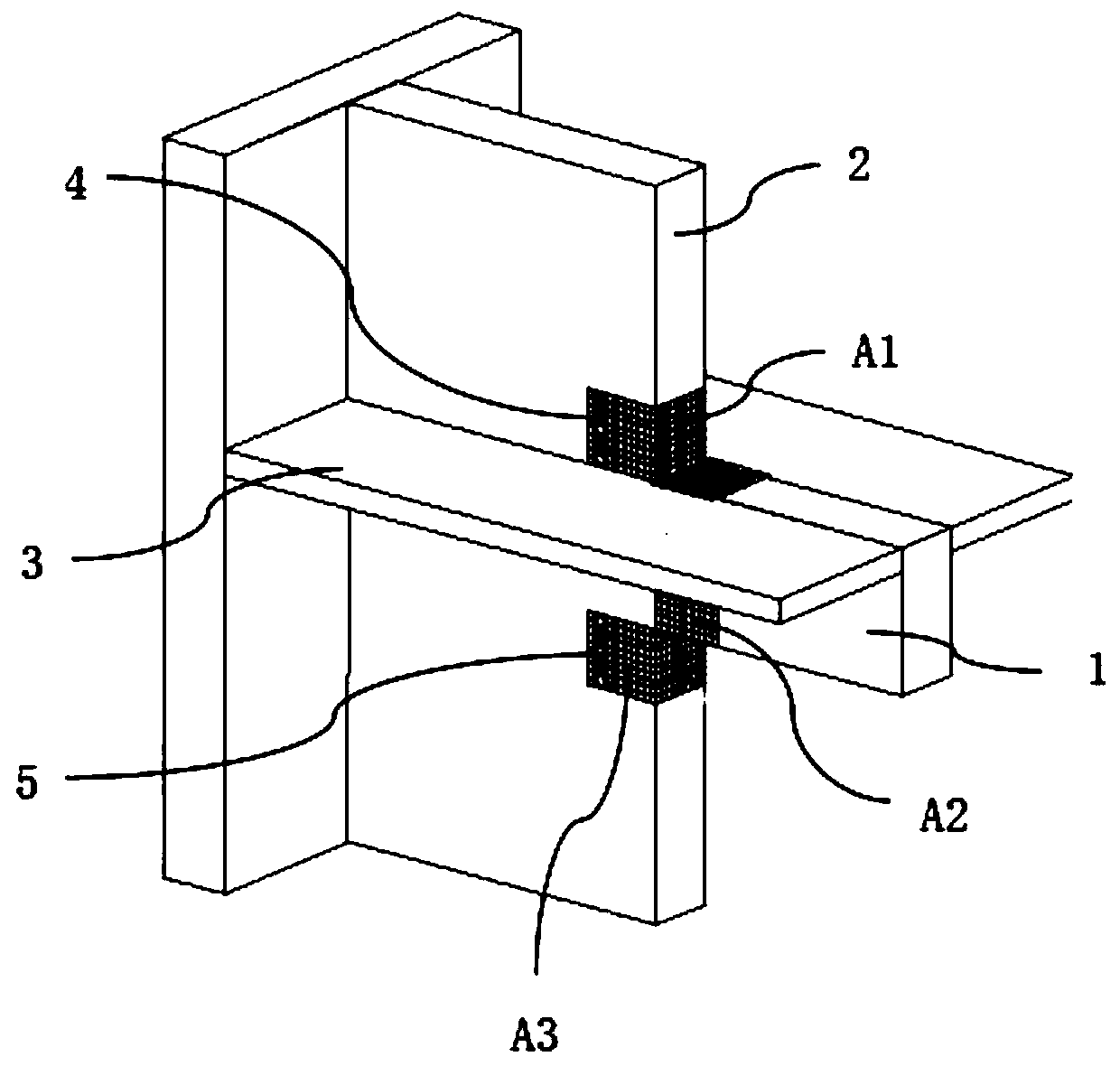
[0034] The invention provides a method for flexurally reinforcing beam ends with floor slabs, such as image 3 As shown, the beam end mentioned in this embodiment is provided with a wall or column 2, and the floor 3 is vertically connected with the beam 1, wall o...


PUM


Abstract

The invention belongs to the technical field of seismic reinforcement and discloses a method for anti-bending reinforcement of a beam end with a floor, wherein a wall or a pillar is disposed at the beam end; the floor is in perpendicular connection to a beam, the wall or the pillar; and composite mortar reinforced by a CFRP mesh is paved to an L-shaped connecting surface between the beam and the wall or the pillar for reinforcement. The method disclosed by the invention has the beneficial effects that based on characteristics of the CFRP mesh that the mesh is light, high in strength and modulus, flexible and easy in construction, easy in anchoring, overlapping and positioning, durable, anti-corrosion, anti-fatigue, anti-magnetic, anti-shielding, and anti-stripping and can reduce thicknessof a reinforcement layer, the CFRP mesh is built in the high-performance cement composite mortar for reinforcement of parts with complicated structures, so various adverse factors of reinforcement with various composite materials which take a traditional rebar mesh as a reinforcement phase can be remedied. The high-strength CFRP mesh is paved to the L-shaped connecting surface between the beam andthe wall or the pillar in an L-shaped manner, so the reinforcement layer formed through combination of the CFRP mesh and the subsequent cement composite mortar can give full play to an anti-tension effect.

Description

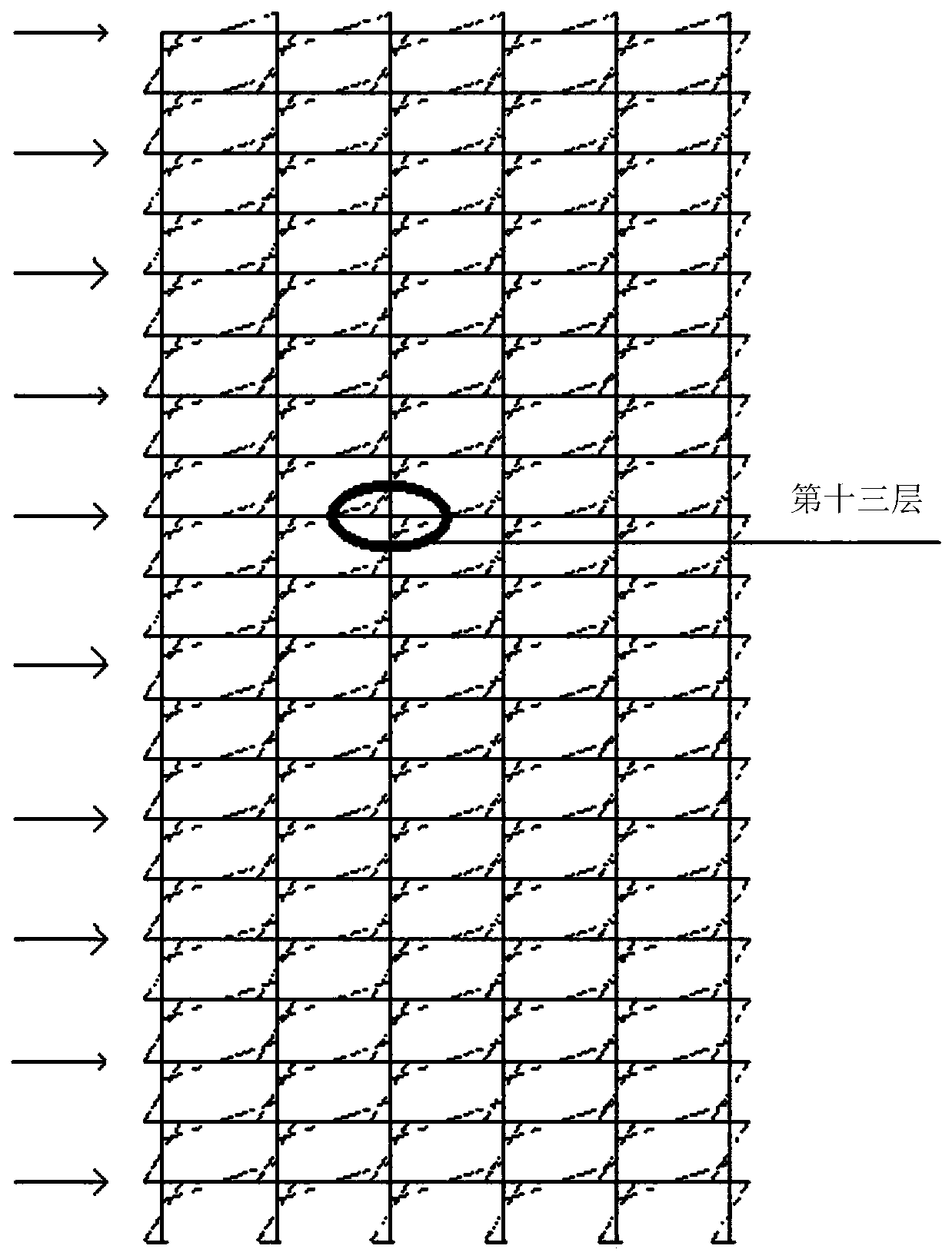
technical field [0001] The invention relates to the technical field of seismic strengthening, and more specifically, relates to a method for performing bending resistance strengthening on a beam end with a floor slab. Background technique [0002] Under the horizontal earthquake or wind load of reinforced concrete short-leg shear wall structure and reinforced concrete cast-in-place frame structure, the beam ends, wall and column ends at the joints are subjected to large bending moments, such as figure 1 shown. [0003] Due to the influence of design and construction or other factors, there may be insufficient flexural longitudinal reinforcement between the beam end and the wall and column end at the joint, and the bending failure of the beam end, wall and column end is prone to occur under the action of horizontal earthquake or wind load . [0004] However, the coupling beams in the reinforced concrete short-leg shear wall structure and the frame beams in the reinforced co...

Claims


Application Information

Patent Timeline
Patent Type & Authority Applications(China)
IPC IPC(8): E04G23/02
CPCE04G23/0218
Inventor 蒋隆敏竹永恒龚鑫
Owner HUNAN UNIV OF TECH
Learn More