Method for monitoring mutual effect of fouling organisms and calcium-magnesium deposited layer in marine environment

A technology of fouling organisms, calcium and magnesium deposition, applied in measuring devices, instruments, scientific instruments, etc., can solve the problems of corrosion damage to steel structures, threats to the safety of steel structures, etc., to ensure sealing problems, avoid galvanic corrosion, and measure technology. simple effect

Pending Publication Date: 2019-11-01
于振花 +2
View PDF0 Cites 2 Cited by
  • Summary
  • Abstract
  • Description
  • Claims
  • Application Information

AI Technical Summary

Problems solved by technology

[0002] In the actual marine environment, the attachment of marine organisms has caused serious corrosion damage to the steel structure, which not only caused huge economic losses, but also posed a serious threat to the safety of the steel structure.

Method used


Image

  • Method for monitoring mutual effect of fouling organisms and calcium-magnesium deposited layer in marine environment
  • Method for monitoring mutual effect of fouling organisms and calcium-magnesium deposited layer in marine environment
  • Method for monitoring mutual effect of fouling organisms and calcium-magnesium deposited layer in marine environment

Examples


Embodiment 1

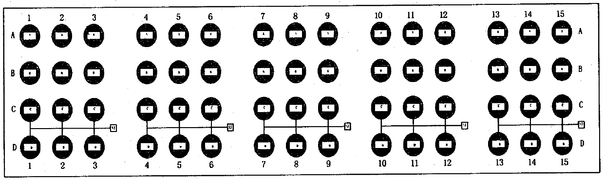
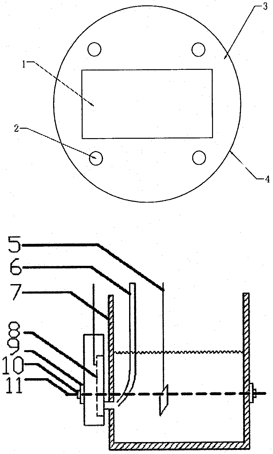
[0028] Such as Figure 1-2 As shown, the real sea experimental device includes a frame, a carbon steel electrode to be measured and a sacrificial anode; the sacrificial anode is fixed on the frame and is coupled with the Q235 steel electrode to be measured; the Q235 steel electrode to be measured has a The mold is filled with epoxy resin between the mold and the Q235 steel to be tested; multiple holes are opened in the filled epoxy resin along the axial direction, and a polymer tube is inserted in each hole. The sacrificial anode is an anode alloy (Zn-Al-Cd). The carbon steel electrode to be tested is fixed on the frame through a polymer tube.

[0029] The material of the annular mold in the real sea experimental device is PVC, and the material of the frame is polyethylene.

[0030]All joints or welding points in the real sea experimental device were sealed with insulating tape and epoxy resin.

Embodiment 2

[0032] The making and testing mode of the actual sea experiment device used in the present invention:

[0033] a. Design and process the corresponding polyethylene frame according to the quality requirements and dimensions, and the ring mold suitable for covering the carbon steel test piece to be tested.

[0034] b. Choose Q235 carbon steel as the carbon steel test piece to be tested, and prepare the test electrode. The Q235 carbon steel is in the shape of a cuboid, and it is packaged in the ring mold that has been made with non-conductive epoxy resin, and the sample is placed in the epoxy resin. Each of the four top ends of the tube is embedded with a polymer tube, and the length of the polymer tube should be consistent with the thickness of the epoxy resin.

[0035] c. Polish the working surface of the prepared test electrode with No. 800 and No. 1200 metallographic sandpaper in turn, then wipe the working surface with absolute ethanol until the surface is smooth, and put it...

Embodiment 3

[0039] Such as image 3 As shown, the main part of the electrochemical test device is a square groove made of organic glass, and a circular hole is opened on one side of the groove There is a rubber gasket embedded in the round hole for sealing between the hole and the sample. Select a certain area of ​​the real sea sample to be tested as the test point, cover the area on the hole, and fix it with a bracket.

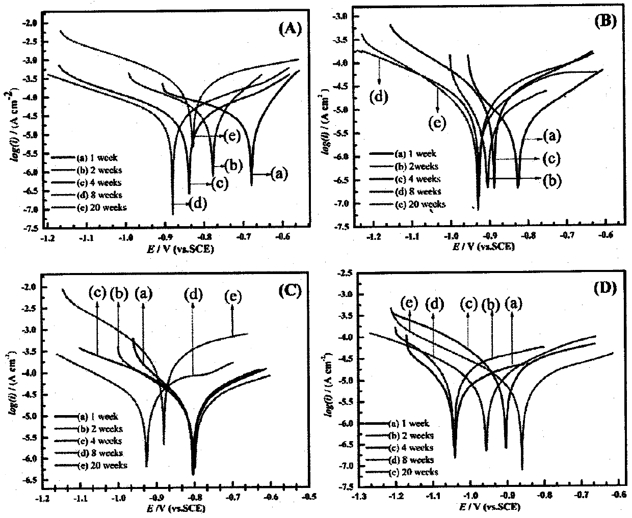
[0040] The electrochemical test device adopts the commonly used three-electrode system, the saturated calomel electrode (SCE) is used as the reference electrode, and the platinum sheet electrode is used as the counter electrode. All electrochemical tests were carried out in fresh seawater.


PUM


Abstract

The invention relates to a method for monitoring mutual effect of fouling organisms and a calcium-magnesium deposited layer in a marine environment, and belongs to the technical field of marine fouling organisms. The method is characterized in that used experimental devices comprise a marine experimental device and an electrochemical testing device. The marine experimental device comprises a testframe, a to-be-measured Q235 steel electrode and a sacrificial anode.

Description

technical field [0001] The invention relates to a method for monitoring the interaction between fouling organisms and cathodic protection calcium and magnesium deposits in the marine environment, and belongs to the technical field of fouling biological corrosion testing. Background technique [0002] In the actual marine environment, the attachment of marine organisms has caused serious corrosion damage to the steel structure, which not only caused huge economic losses, but also posed a serious threat to the safety of the steel structure. Cathodic protection is a kind of anti-corrosion technology widely used in the gradually prosperous marine engineering. It can effectively control the damage caused by corrosion and protect the steel structure, thereby reducing unnecessary economic losses caused by corrosion and ensuring the safety of the steel structure. Safety. The effect of cathodic protection on steel structures is directly related to the safety and service life of stee...

Claims


Application Information

Patent Timeline
Patent Type & Authority Applications(China)
IPC IPC(8): G01N17/02G01N27/26C23F13/02
CPCC23F13/02G01N17/006G01N17/02G01N27/26
Inventor 于振花安乾张杰宋积文
Owner 于振花
Why Eureka
Try Eureka