
Liquid dielectric constant sensor based on miniaturized dielectric resonator antenna and application

A dielectric resonator and dielectric constant technology, applied in dielectric performance measurement, instruments, material capacitance, etc., can solve the problems of large size, large sensor volume, pollution, etc., and achieve antenna size reduction, high sensitivity characteristics, and wide application. Foreground effect

Active Publication Date: 2019-11-01
XIDIAN UNIV
View PDF12 Cites 4 Cited by
  • Summary
  • Abstract
  • Description
  • Claims
  • Application Information

AI Technical Summary

Problems solved by technology

However, this method often requires a certain volume of liquid to complete the detection, resulting in waste of liquid and environmental pollution.
[0007] To sum up, the problems existing in the prior art are: most of the liquid permittivity sensors based on the resonator antenna design are relatively large in size, and the amount of liquid to be tested is also required to be large, which is likely to cause waste of liquid and environmental pollution
Due to its advantages of low cost and high efficiency, dielectric resonator antennas have attracted widespread attention. Cylindrical dielectric resonator antennas working in HEM mode have been introduced into the design of liquid sensors. However, due to their working modes, they cannot Realize the miniaturization design of the antenna, making the sensor volume larger

Method used


Image

  • Liquid dielectric constant sensor based on miniaturized dielectric resonator antenna and application
  • Liquid dielectric constant sensor based on miniaturized dielectric resonator antenna and application
  • Liquid dielectric constant sensor based on miniaturized dielectric resonator antenna and application

Examples


Embodiment Construction

[0033] In order to make the object, technical solution and advantages of the present invention more clear, the present invention will be further described in detail below in conjunction with the examples. It should be understood that the specific embodiments described here are only used to explain the present invention, not to limit the present invention.

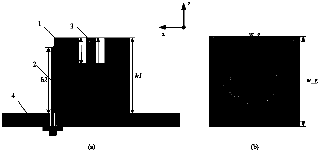
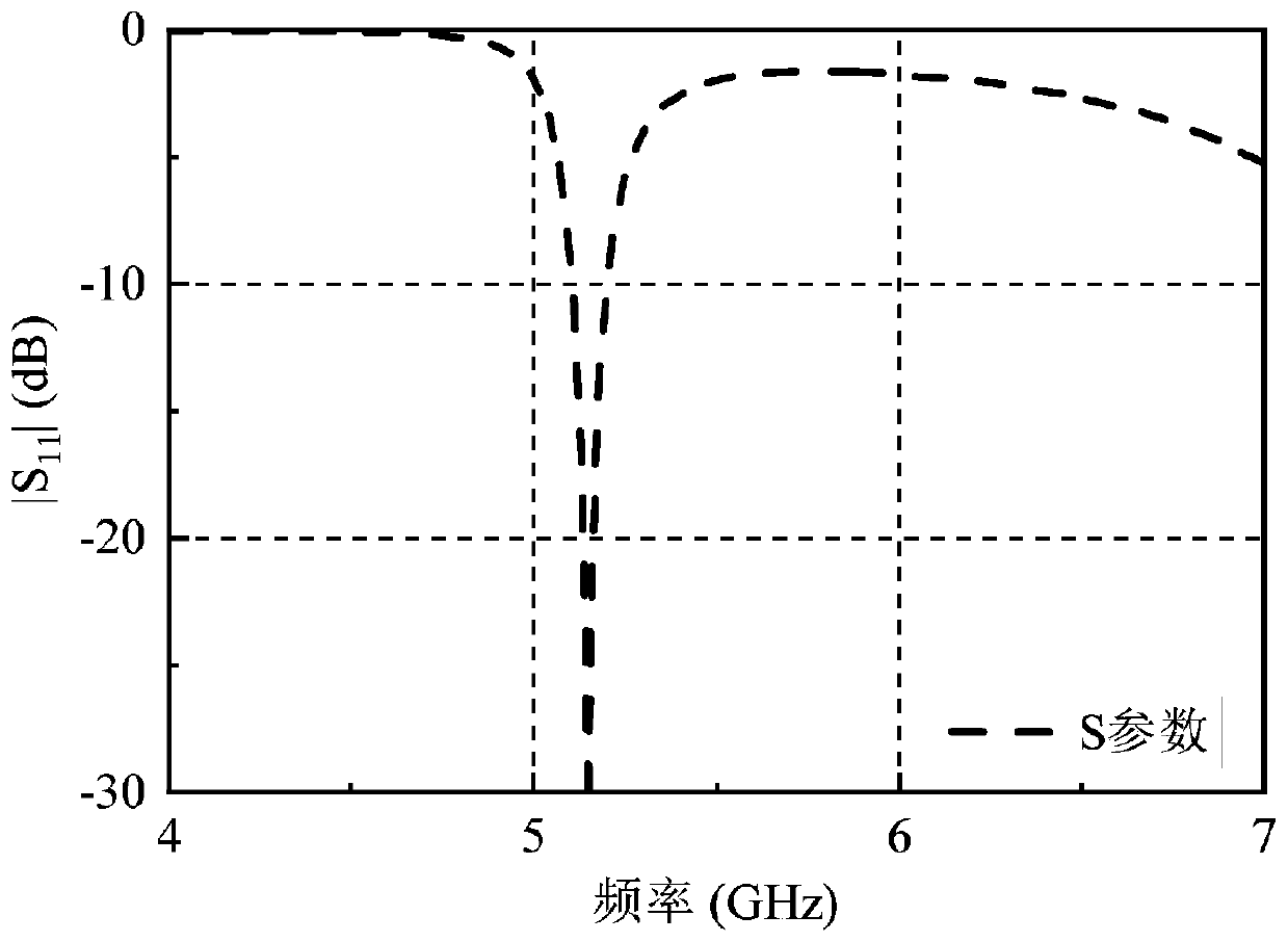
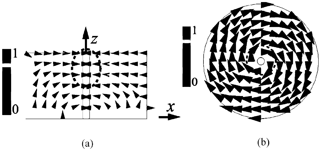
[0034] Aiming at the problem that most of the existing liquid permittivity sensors designed based on the resonator antenna are relatively large in size and require a large amount of liquid to be measured. In the present invention, by introducing a short-circuit column in the middle of the traditional cylindrical dielectric resonator antenna, the original fundamental mode is replaced by the HEM 11δ Mode shift to TM 10δ mode, greatly reducing the TM 10δ mode, effectively reducing the size of the antenna. The invention places the micro-cavity at the place where the electric field intensity of the dielectric resonator antenn...


PUM

PropertyMeasurementUnit
radiusaaaaaaaaaa
radiusaaaaaaaaaa
radiusaaaaaaaaaa

Abstract

The invention belongs to the technical field of liquid characteristic detection, and discloses a liquid dielectric constant sensor based on a miniaturized dielectric resonator antenna and an application, wherein a micro cavity is introduced at the top of the dielectric resonator, and a shorting pin is introduced in the middle of the dielectric resonator; the feed structure is a feed probe on one side of the resonator; the feed probe is located on one side of the dielectric resonator and is in close contact with the side of the dielectric resonator; the shorting pin introduced in the middle ofthe dielectric resonator is connected to the floor; and the dielectric resonator and feed structure are on the same side of the floor. The liquid dielectric constant sensor provided by the invention has the characteristics of small volume, simple structure and high sensitivity, and has broad application prospects in the field of liquid sensors. By introducing the shorting pin in the middle of thecylindrical dielectric resonator antenna, the fundamental mode thereof is changed from HEM11delta mode into TM10delta mode. Moreover, the TM10delta mode is also greatly reduced compared to conventional cylindrical dielectric resonator antennas.

Description

technical field [0001] The invention belongs to the technical field of liquid characteristic detection, in particular to a liquid dielectric constant sensor based on a miniaturized dielectric resonator antenna and its application. Background technique [0002] At present, the closest existing technology: microwave sensors have a wide range of applications in daily life and industrial production applications. Due to the high working frequency band (often GHz frequency band), microwave sensors have the advantages of small size, high sensitivity, strong reliability, no pollution and low cost, and are widely used in temperature detection, building form detection, biomedicine and chemical industry field. Common microwave sensor applications include temperature sensors, tension and object deformation sensors, and material dielectric property sensors, among others. Liquid dielectric property sensors have broad prospects in food inspection, medical testing and chemical composition...

Claims


Application Information

Patent Timeline
Patent Type & Authority Applications(China)
IPC IPC(8): G01R27/26G01N27/22
CPCG01N27/221G01R27/2635G01R27/267G01R27/2676
Inventor 任建黄汝瑶尹应增
Owner XIDIAN UNIV
Learn More