Tin welding machine equipment

A soldering machine and equipment technology, applied in the direction of welding equipment, metal processing equipment, auxiliary devices, etc., can solve the problems of low soldering efficiency and low efficiency

Pending Publication Date: 2019-11-15
深圳市大圣神通机器人科技有限公司
View PDF0 Cites 8 Cited by
  • Summary
  • Abstract
  • Description
  • Claims
  • Application Information

AI Technical Summary

Problems solved by technology

In the soldering process, the wire needs to be stripped. Since the wire stripping is a complicated process, if it is handled manually, the efficiency is extremely low. Therefore, a wire stripping equipment is needed to solve this problem.
[0006] There are multiple wire cores in

Method used


Image

  • Tin welding machine equipment
  • Tin welding machine equipment
  • Tin welding machine equipment

Examples


Embodiment 1

[0087] Embodiment 1, the concrete structure of the present invention is as follows:

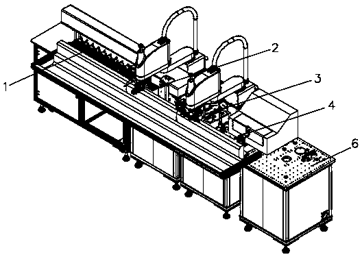
[0088] Please refer to the attached Figure 1-22 , a kind of soldering machine equipment of the present invention, this soldering machine equipment comprises:

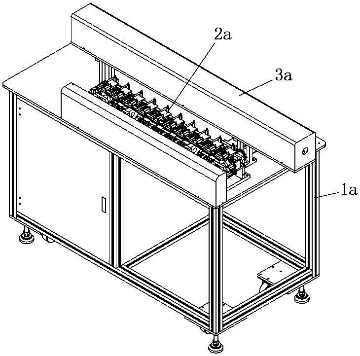
[0089] One is located at the feeding buffer device 2a on the first frame 1a, comprises a chain conveyor belt 29a and drives described chain conveyor belt 29a to do the 4th driving mechanism of intermittent rotation, and described chain conveyor belt 29a is provided with etc. The wire clamping assembly 24a used for clamping the wire, the wire clamping assembly 24a moves with the chain conveyor belt 29a, and the wire clamping assembly 24a moves along a pair of first slide rails 25a when moving upward ;

[0090] A wire stripping mechanism 2b arranged on the second frame 7b, the upper end of the second frame 7b is provided with a first platform, the stripping mechanism 2b includes a first four-axis manipulator 1b, a pre-cut assembly 3b, a...

Embodiment 2

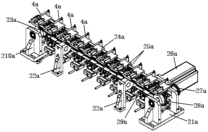
[0095] Such as Figure 2-4 As shown, the working principle of the loading buffer device 2a is as follows:

[0096] The two ends of the chain conveyor belt 29a are respectively sleeved on the driving gear 28a and the first driven gear 23a, wherein: the driving gear 28a is sleeved on a rotating shaft, and the rotating shaft is set on a right chain support 21a and its One end passes through the side plate of the right chain bracket 21a and the end is fixed with a second driven gear 27a, which is driven to rotate by the fourth drive mechanism; the first driven gear 23a covers Connected on a rotating shaft, the rotating shaft is mounted on a left chain support 210a; the fourth driving mechanism is a stepping motor 26a, and the driving end of the stepping motor 26a is connected to a gear, which is connected to the second driven gear 27a is provided with synchronous belt.

[0097] The wire clamping assembly 24a includes:

[0098] A fixture mounting plate, the left and right sides ...

Embodiment 3

[0106] Such as Figure 5-15 , the following is the structure and operating principle of the wire stripping mechanism 2b:

[0107] 1. The structure of wire stripping mechanism 2b is as follows:

[0108] The first four-axis manipulator 1b includes a motor 11b, a rocker arm 12b, a limit elbow 15b, a claw mounting arm 13b and a height adjuster 14b, and the motor 11b is vertically fixed on the first platform, and its driving The rocker arm 12b is connected upwards, the swing arm 12b moves in a horizontal plane, and the upper side of the other end is pivotally connected to the mechanical claw installation arm 13b, and the mechanical claw installation arm 13b is away from one end of the swing arm 12b A height adjuster 14b that can be adjusted in height is installed in the clip hole, and a rotatable limit elbow 15b is connected between the upper end of one end of the rocker arm 12b and the housing of the motor 11b. The height adjuster The lower end of 14b is connected to the jaw ass...


PUM


Abstract

The invention discloses tin welding machine equipment. The tin welding machine equipment comprises a loading buffer device, a wire material peeling mechanism, a tin dipping mechanism, a tin welding mechanism and a material receiving part from a charge end to a discharge end. According to the tin welding machine equipment, the loading buffer device adopts a stepper motor for intermittently feeding,and wire materials have a buffer function in the area, and do not influence a tin welding speed. The tin welding machine integrates manipulator feeding, wire material pre-cutting, wire material finish cutting, a laser cutting device used for cutting off the skins of the wire materials, and a double-sided peeling mechanism peeling the inner core wire skins of the wire materials and pulling out theinner core wire skins. According to the tin welding machine equipment, the wire skins do not need to be manually peeled, so that the labor cost is saved, and the peeling machining efficiency for thewire materials is increased. An assembly connector integrates material taking, flux bonding, tin bonding, wire arrangement and separation, and tin welding; and a clamping device is moved to a materialtaking station, a flux bonding station, a tin bonding station, a wire arrangement and separation station, and a tin welding station through a four-axis manipulator, so that the tin welding efficiencyis increased.

Description

technical field [0001] The invention relates to the technical field of soldering, in particular to a soldering machine equipment. Background technique [0002] Soldering is a welding method that uses low melting point metal solder to heat and melt, penetrate and fill the gap at the joint of metal parts. Because the solder is often a tin-based alloy, it is named. Soldering irons are commonly used as heating tools and are widely used in the electronics industry. [0003] In the soldering of data lines, it needs to be used for soldering equipment. [0004] Existing automatic soldering machines include multiple devices, such as wire feeding equipment, soldering equipment, and tin feeding mechanism. Since soldering needs to be carried out step by step, a buffer device needs to be installed on the wire feeding equipment. [0005] The data line is provided with an outer sheath and an inner core, and the inner core is also provided with an inner core wire sheath. In the solderin...

Claims


Application Information

Patent Timeline
IPC IPC(8): B23K3/00B23K3/08
CPCB23K3/00B23K3/08
Inventor 邹志勇
Owner 深圳市大圣神通机器人科技有限公司
Why Eureka
Try Eureka