Single mode fiber

A single-mode optical fiber and optical fiber technology, which is applied in cladding optical fiber, multi-layer core/clad optical fiber, light guide, etc., can solve the problems of unmentioned loss and attenuation characteristics, high cut-off bending wavelength, high dispersion, etc., to achieve Effects of improving the accuracy of the refractive index profile, improving the bending resistance, and improving the bending performance

Inactive Publication Date: 2019-11-15
YANGTZE OPTICAL FIBRE & CABLE CO LTD
View PDF5 Cites 14 Cited by
  • Summary
  • Abstract
  • Description
  • Claims
  • Application Information

AI Technical Summary

Problems solved by technology

[0007] In Chinese patent CN101680994A, the applicant describes a fiber with small bending loss, but does not mention the loss and attenuation characteristics of the 5mm bending radius at 1550nm, and the relative refractive index difference of the depressed cladding is -7.28×10 -3 ~-2.62×10 -2 Considering that its deep sag will cause excessively high cut-off bend wavelength and high dispersion, and it is prone to multi-path interference (MPI) problems during optical fiber transmission, which will affect the compatibility of optical fibers and is not conducive to bending insensitive optical fibers Application in existing communication network
This structure is used to reduce the bending loss, and the prepared optical fiber also conforms to the G.652 standard, but it is typically only suitable for use under a bending radius of 7.5mm. The patent does not give an example of bending loss with a bending radius of 5.0mm and Specific parameters
At the same time, it can be seen that the radius of the intermediate cladding in the refractive index profile is 18um-20um, while the fluorine-doped second depressed cladding is wider, reaching 25um-40um, and the proportion of the fluorine-doped layer in the optical fiber is significantly higher. The designed The complex structure of multi-layer sunken cladding and intermediate cladding is not conducive to its large-scale production and practical application

Method used


Image

  • Single mode fiber
  • Single mode fiber
  • Single mode fiber

Examples


Embodiment Construction

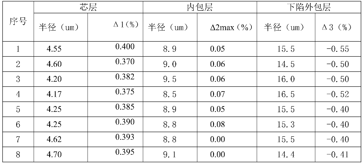
[0040] Detailed examples will be given below to further illustrate the present invention.

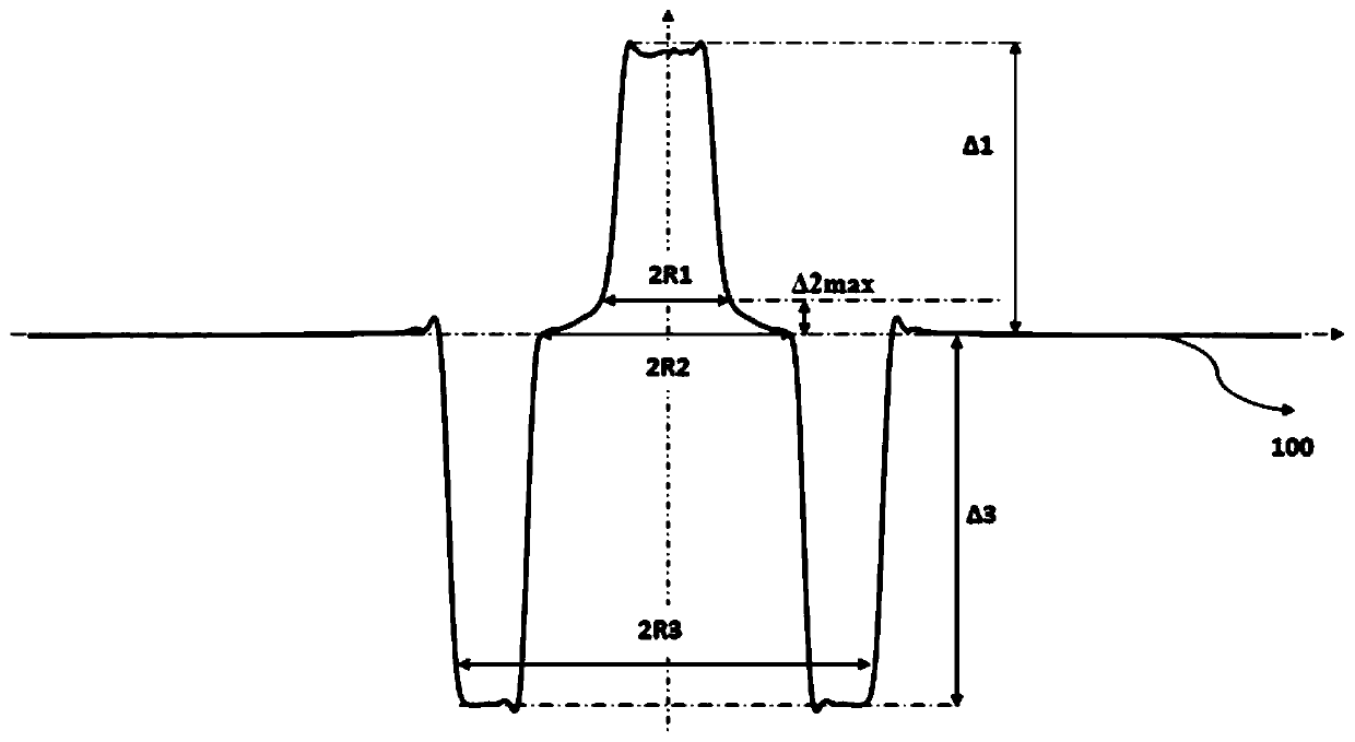
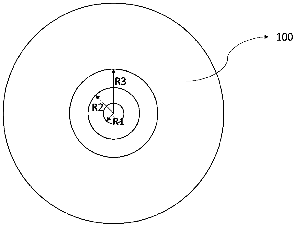
[0041] An optical fiber includes a core, an inner cladding, a depressed cladding and an outer cladding. The diameter of the core layer is 2R1, the relative refractive index difference is Δ1, the diameter of the inner cladding is 2R2, and the inner cladding has a relative refractive index difference that decreases from the inner edge to the outer edge, wherein the maximum relative refractive index difference is Δ2max, The relative refractive index difference at the outer edge, that is, the junction between the inner cladding and the sunken cladding is 0.0%, the diameter of the sunken cladding is 2R3, the relative refractive index difference is Δ3, and the outer cladding 100 is pure silicon dioxide outer cladding. The core layer and the inner cladding layer are composed of a silica glass layer doped with germanium or germanium-chlorine co-doped, the sunken cladding layer is a silica glass...


PUM


Abstract

The invention relates to a low-bend loss single mode fiber comprising a core and a cladding, wherein the cladding comprises an inner cladding, a depressed cladding and an outer cladding from the inside to the outside; the core has a diameter 2R1 of 8.2[mu]m-9.4[mu]m and a relative refractive index difference delta1 of 0.360%-0.420%; the inner cladding has a diameter 2R2 of 16.0[mu]m-19.0[mu]m anda relative refractive index difference gradually changing from the inner edge to the outer edge, wherein the maximum relative refractive index difference delta2max is 0.02%-0.10%, and the outer edge,that is, the junction between the inner cladding and the depressed cladding has a relative refractive index difference of 0.0%; the depressed cladding has a diameter 2R3 of 28.0[mu]m-35.0[mu]m and a relative refractive index difference delta3 of 0.40%-0.65%, and the outer cladding is a pure silica outer cladding. The single mode fiber provided by the invention has a low bending loss under the condition of ensuring a large mode field diameter of the optical fiber due to a reasonable configuration of the refractive index profile to improve the bending performance of the optical fiber, and the bending performance of the optical fiber exceeds a G.657.B3 standard to meet the needs of access networks and some miniaturized optical devices.

Description

technical field [0001] The invention relates to a single-mode optical fiber with low bending loss used in an optical communication transmission system. The optical fiber has low bending loss under a small bending radius, and belongs to the technical field of access network optical communication. Background technique [0002] With the continuous development of optical fiber transmission technology, fiber-to-the-home and fiber-to-the-desktop have become an important development direction of communication access network construction. Optical fiber as a transmission medium plays a vital role in it. In the actual laying and configuration of FTTx optical fiber lines, it is often necessary to perform various operations on optical fibers indoors and in narrow environments, such as installing at right-angled corners of walls, winding optical fibers in increasingly miniaturized storage boxes to handle optical fibers Lengthy, so it is necessary to design and develop optical fibers wit...

Claims


Application Information

Patent Timeline
Patent Type & Authority Applications(China)
IPC IPC(8): G02B6/028G02B6/036G02B6/02G02B1/00
CPCG02B1/00G02B6/02009G02B6/0283G02B6/03638
Inventor 吴超张磊杨柳波吴俊王洋罗杰
Owner YANGTZE OPTICAL FIBRE & CABLE CO LTD
Why Eureka
Try Eureka