A laser measurement method and system for the thickness of a transparent object

A transparent object, laser measurement technology, applied in the field of measurement, can solve the problems of poor measurement accuracy, low accuracy, thickness measurement results change, etc., to solve the problem of thickness inconsistency, improve accuracy and consistency, and take into account the effect of accuracy and speed

Active Publication Date: 2020-11-20
SHANGHAI JIAOTONG UNIV
View PDF1 Cites 0 Cited by
  • Summary
  • Abstract
  • Description
  • Claims
  • Application Information

AI Technical Summary

Problems solved by technology

The serious disadvantage of this method is: the measured transparent object must be placed on the opaque base surface to complete the thickness measurement. This condition is often not available in the actual workplace, and the distance measurement of the transparent object Depends on thickness measurement, its accuracy is much lower than that of thickness measurement, so its use is limited, and it is rarely used in practice
However, this method has always had a serious defect: when the relative position between the transparent object to be measured and the measuring device changes, the thickness measurement results will change significantly and lose the due measurement accuracy
However, due to the use of two laser displacement sensors, the patented measurement system has complex composition, high cost, and large device junction volume. After the laser is vertically incident, most of the energy is reflected or projected, and the amplitude of the imaging waveform will be very low. Measurement accuracy Poor, at the same time, the thickness measurement problem caused by different distances has not been overcome, and it is not advisable

Method used


Image

  • A laser measurement method and system for the thickness of a transparent object
  • A laser measurement method and system for the thickness of a transparent object
  • A laser measurement method and system for the thickness of a transparent object

Examples


Embodiment Construction

[0039] The present invention will be described in detail below in conjunction with specific embodiments. The following examples will help those skilled in the art to further understand the present invention, but do not limit the present invention in any form. It should be noted that those skilled in the art can make several modifications and improvements without departing from the concept of the present invention. These all belong to the protection scope of the present invention.

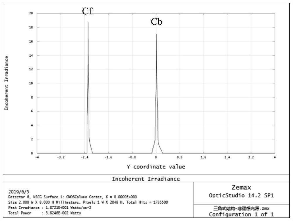
[0040] Aiming at the problem that the existing laser measurement of the thickness of transparent objects cannot adapt to position changes, the present invention proposes an adaptive laser measurement method and system for non-contact measurement of the thickness of transparent objects. The change law of the centroid spacing-thickness of the imaging waveform seems to be in the form of a polynomial. The thickness characteristic parameters at each position are obtained by curve fitting, and then the t...


PUM


Abstract

The invention provides a laser measurement method and system for a thickness of a transparent object. The method comprises the steps as follows: a laser beam emitted from a laser passes through a diversing lens and then forms a focused laser beam; the focused laser beam is projected to the front surface of a to-be-measured transparent object; the beam reflected from the front surface of the to-be-measured transparent object passes through a light filter and a receiving lens and then forms one front surface imaging waveform on a linear CMOS device; the beam refracted from the front surface of the to-be-measured transparent object reaches the rear surface of the to-be-measured transparent object and forms one rear surface imaging waveform on the linear CMOS device after reflection and secondary refraction through the rear surface of the to-be-measured transparent object; the center-of-mass coordinates of the front surface imaging waveforms correspond to the positions of the front surfaceone by one; and measurement of the thickness of the transparent object can be achieved according to a laser triangulation principle. The laser measurement method and system are capable of obtaining the position of the front surface and a thickness value of the transparent object at the same time, can automatically adapt to the position change of the front surface to obtain a normalized accurate thickness measurement result and have wider practicability and versatility.

Description

technical field [0001] The invention relates to a measurement technology, in particular to a laser measurement method and system for non-contact measurement of the thickness of a transparent object. Background technique [0002] Various transparent objects represented by glass are more and more widely used in various fields of the national economy such as electronic information, transportation, aerospace, and architectural decoration. The thickness measurement of a transparent object (such as glass) is an indispensable routine link both for its own production, processing and quality control, and for the user of the transparent object. [0003] The traditional method of measuring the thickness of transparent objects is mainly to use tools such as screw micrometers and vernier calipers for manual measurement. Due to the poor flexibility and low efficiency of this manual contact measurement, and it is easy to cause scratches on the surface of transparent objects, it is gradual...

Claims


Application Information

Patent Timeline
Patent Type & Authority Patents(China)
IPC IPC(8): G01B11/06G01B11/03
CPCG01B11/03G01B11/06
Inventor 赵辉陶卫吕娜刘凯媚南卓江崔斌李智冯宇孙昊
Owner SHANGHAI JIAOTONG UNIV
Why Eureka
Try Eureka