
Channel millimeter wave periodic crossed array antenna

A technology of cross array and array antenna, which is applied in the field of channel-type millimeter-wave periodic cross-array antenna, can solve the problems of system complexity and cost increase, not the implementation method of millimeter-wave array antenna, etc., to improve the radiation bandwidth and gain, improve The effect of probing throughput and reducing scan time

Inactive Publication Date: 2019-11-19
CHONGQING INST OF GREEN & INTELLIGENT TECH CHINESE ACADEMY OF SCI
View PDF4 Cites 3 Cited by
  • Summary
  • Abstract
  • Description
  • Claims
  • Application Information

AI Technical Summary

Problems solved by technology

However, the system complexity and cost will increase significantly, and it is not a feasible implementation method of mmWave array antenna

Method used


Image

  • Channel millimeter wave periodic crossed array antenna
  • Channel millimeter wave periodic crossed array antenna
  • Channel millimeter wave periodic crossed array antenna

Examples


Embodiment

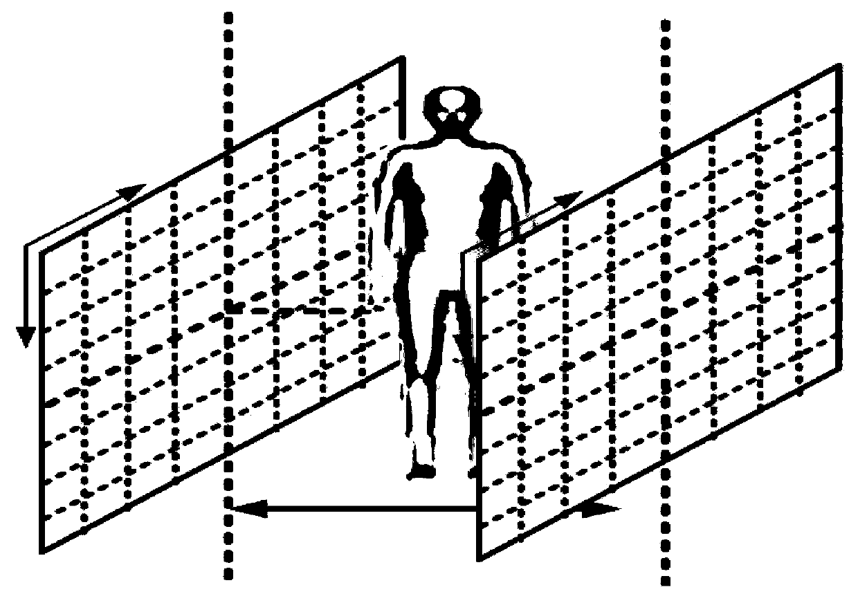
[0050] A channel-type millimeter-wave periodic cross array antenna consists of two sets of identical periodic cross array antennas, which are placed on both sides of the passageway, such as figure 1shown. Two sets of array antennas work independently, simultaneously radiating and receiving millimeter-wave signals to the subject's body, and after each imaging, they are synthesized into a 360° three-dimensional image of the human body.

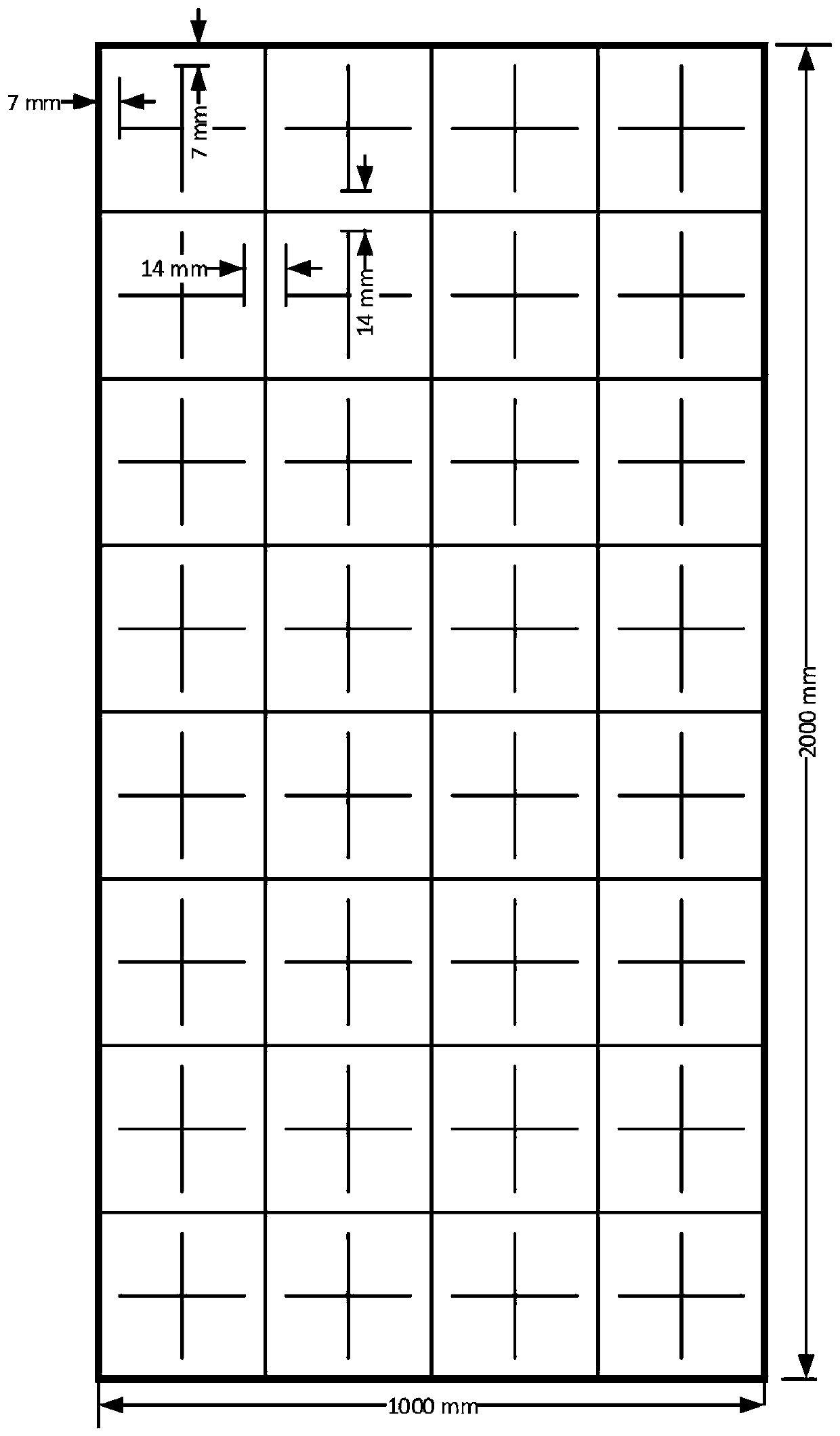
[0051] The periodic cross array antenna consists of 32 cross arrays, such as figure 2 shown. The horizontal direction is divided into four columns, and the vertical direction is divided into 8 rows. The size of each cross array is 0.5m*0.5m, forming a planar array of 1m*2m. The distance between the outermost antenna of the cross array and the horizontal and vertical edges of the plane is 7mm, and the horizontal and vertical distance between the cross arrays is 14mm.

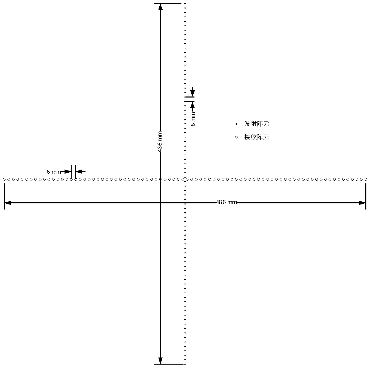
[0052] The cross array antenna consists of 82 transmitting array elements ...


PUM


Abstract

The invention relates to a channel millimeter wave periodic crossed array antenna and belongs to the technical field of antennas. The channel millimeter wave periodic crossed array antenna consists oftwo identical groups of periodic crossed array antennas, which are disposed on both sides of a pedestrian flow channel. Each periodic crossed array antenna consists of 32 crossed arrays which are divided into four columns in the horizontal direction and eight rows in the vertical direction. Each crossed array antenna is composed of 82 transmitting array elements and 82 receiving array elements. The transmitting array elements and the receiving array elements are arranged linearly and uniformly in the vertical and horizontal directions respectively. The array elements have a spacing of 6mm anda synthetic aperture length of 486mm. The transmitting and receiving array elements both use a substrate integrated waveguide and dual-dipole design method, improve a millimeter wave radiation bandwidth and gain, simplify the feed structure, and reduce an array element size. No mechanical movement or rotation is required and a human body can be imaged within 360 degrees. The crossed arrays use time-division multiplexing or frequency-division multiplexing to achieve the fast scanning of the antenna and increase the imaging speed.

Description

technical field [0001] The invention belongs to the technical field of antennas, and relates to a channel type millimeter wave periodic cross array antenna. Background technique [0002] With the advantages of good penetration, high resolution, and low electromagnetic radiation dose, millimeter wave signals are increasingly used in the field of security imaging. The millimeter-wave human body security detector uses the millimeter-wave transmitter to radiate millimeter-wave into space through the transmitting antenna, and then the scattered millimeter-wave through the target is received by the receiving antenna, and uses the amplitude and phase information of the echo signal to perform three-dimensional imaging of the target. In this process, the antenna plays a vital role as a millimeter-wave transmitting and receiving device. [0003] Most of the existing millimeter-wave array antennas adopt a one-dimensional linear structure, which is composed of a plurality of transmitti...

Claims


Application Information

Patent Timeline
Patent Type & Authority Applications(China)
IPC IPC(8): H01Q21/06H01Q1/38H01Q1/22G01V8/00G01V8/10
CPCG01V8/005G01V8/10H01Q1/225H01Q1/38H01Q21/061
Inventor 崔洪亮王忠民常天英郭企嘉
Owner CHONGQING INST OF GREEN & INTELLIGENT TECH CHINESE ACADEMY OF SCI
Learn More