Permanent magnet synchronous motor with limited rotation angle

A technology of permanent magnet synchronous motor and limited rotation angle, which is applied to synchronous motors with rotating armature and stationary magnets, electrical components, electromechanical devices, etc., which can solve the problems of high torque density and cramped space, etc. High moment density, improved efficiency, low speed effect

Active Publication Date: 2019-11-19
BEIJING RES INST OF PRECISE MECHATRONICS CONTROLS
View PDF8 Cites 0 Cited by
  • Summary
  • Abstract
  • Description
  • Claims
  • Application Information

AI Technical Summary

Problems solved by technology

The traditional permanent magnet synchronous propulsion motor is to inlay the armature winding in the stator core, which is fixed by the base and the external structure, which is called the stator part; the rotor composed of the permanent magnet, the rotor core

Method used


Image

  • Permanent magnet synchronous motor with limited rotation angle
  • Permanent magnet synchronous motor with limited rotation angle

Examples


Embodiment 1

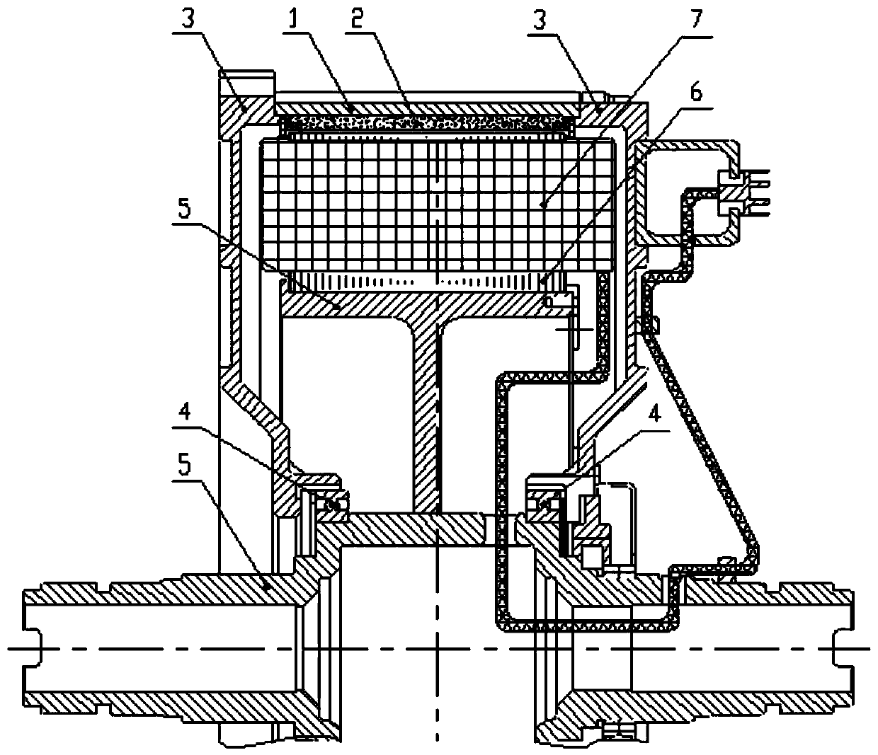
[0035] A limited rotation angle permanent magnet synchronous motor, comprising: a base 1, a permanent magnet 2, an end cover 3; a bearing 4, a rotating shaft 5, an armature core 6, an armature winding 7, and a permanent magnet fixing ring, such as figure 1 As shown; the base 1 is connected with the end cover 3; the permanent magnet 2 is installed on the inner side of the base 1, and the base 1, the permanent magnet 2, and the end cover 3 integrally form a stator; the rotating shaft 5 passes through the bearing 4 is connected with the end cover 3; the armature core 6 is set on the rotating shaft 5; a groove is provided in the armature core 6, and the armature winding 7 is installed in the groove, and the rotating shaft 5. The armature core 6 and the armature winding 7 integrally constitute the rotor; the armature core 6 is located inside the permanent magnet 2 , and a gap is provided between the armature core 6 and the permanent magnet 2 . The permanent magnet fixing ring is in...

Embodiment 2

[0042] A permanent magnet synchronous motor with a limited rotation angle is composed of a base 1, a permanent magnet 2, front and rear end covers, front and rear bearings, inner and outer rotating shafts, an armature core 6 and an armature winding 7.

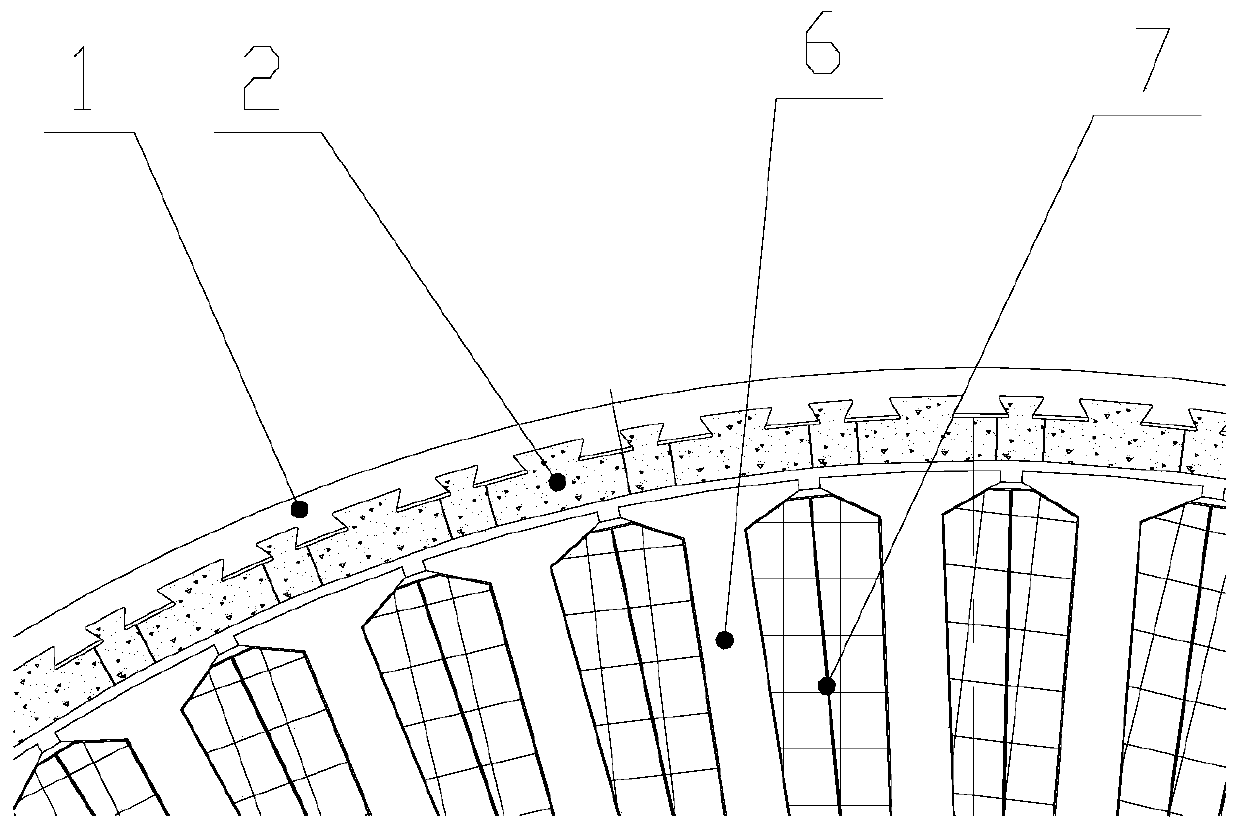
[0043] The armature core 6 is made of stacked high-permeability silicon steel sheets with armature slots. The armature winding 7 is made of high-conductivity materials and embedded in the armature slots of the armature core 6. The winding armature core 6 is shrunk on the outer shaft made of aluminum alloy through interference fit, and the outer shaft and the inner shaft made of No. 45 steel are connected by hinged hole bolts. The overall composition The motor rotor part and the outer shaft part are made of aluminum alloy, which can reduce the weight and moment of inertia of the motor rotor.

[0044] Machine base 1 is made of No. 10 steel material. On the inner circle of machine base 1, there are dovetail grooves with twice the ...


PUM


Abstract

A permanent magnet synchronous motor with a limited rotation angle belongs to the technical field of synchronous motors, and comprises a base 1, a permanent magnet 2 and an end cover 3, a bearing 4, arotating shaft 5, an armature core 6 and an armature winding 7; the base 1 is connected with the end cover 3; the permanent magnet 2 is mounted on the inner side of the base 1, and the base 1, the permanent magnet 2 and the end cover 3 integrally form a stator; the rotating shaft 5 is connected with the end cover 3 through the bearing 4; the armature core 6 sleeves the rotating shaft 5; a grooveis formed in the armature core 6, the armature winding 7 is installed in the groove, and the rotating shaft 5, the armature core 6 and the armature winding 7 integrally form a rotor. The armature core6 is located in the permanent magnet 2, and a gap is arranged between the armature core 6 and the permanent magnet 2. The motor is small in size, high in torque density, low in rotating speed and high in efficiency.

Description

technical field [0001] The invention relates to a limited rotation angle permanent magnet synchronous motor, in particular to a low speed, high efficiency and high torque density limited rotation angle motor. Background technique [0002] The design and development of bionic fish is the crystallization of the integration of many high-tech disciplines, and it is an integrated design system of mechanics, optics, electricity, computer technology, automatic control, material technology, sealing technology and fluid mechanics. Developed countries such as Europe, America and Japan started earlier in the field of theoretical research and design of bionic fish. As a rising star, China has also achieved fruitful results in the research of bionic fish. However, compared with real fish, bionic fish still has a certain gap in swimming speed, maneuverability and swimming efficiency, and more in-depth research on the theory and system design of bionic fish is needed. [0003] The main dr...

Claims


Application Information

Patent Timeline
IPC IPC(8): H02K21/28H02K7/00H02K1/17
CPCH02K1/17H02K7/003H02K21/28H02K2213/03
Inventor 袁静国岳彩锐魏娟赵国平韩柏然李晓贝
Owner BEIJING RES INST OF PRECISE MECHATRONICS CONTROLS
Why Eureka
Try Eureka