Consumption reduction and efficiency improvement system and method suitable for oxidation ditch biological denitrification

A biological denitrification and oxidation ditch technology, which is applied in the system field of reducing consumption and improving efficiency, can solve the problem that it is difficult to control the process parameters in a reasonable range, the effluent water quality cannot reach the ideal target, and the excessive consumption of carbon source and aeration air volume and other problems, to achieve the effect of precise control of aeration volume, high degree of automation, and reduced operating energy consumption

Pending Publication Date: 2019-11-22
浙江海牛环境科技股份有限公司
View PDF14 Cites 4 Cited by
  • Summary
  • Abstract
  • Description
  • Claims
  • Application Information

AI Technical Summary

Problems solved by technology

[0004] In the process of traditional process design and operation, people rely on empirical parameters for aeration rate, aeration area, carbon source dosage, etc., so it is difficult to control all process parameters within a reasonable range
Especially in the balance between nitrification and denitrification in the process of removing total nitrogen, it is difficult for operators to control the relationship between the two, resulting in excessive consumption of carbon sources and aeration air volume, increased operating costs, and poor effluent quality. achieve the desired goal

Method used


Image

  • Consumption reduction and efficiency improvement system and method suitable for oxidation ditch biological denitrification
  • Consumption reduction and efficiency improvement system and method suitable for oxidation ditch biological denitrification
  • Consumption reduction and efficiency improvement system and method suitable for oxidation ditch biological denitrification

Examples


Embodiment Construction

[0049] The present invention will be described in further detail below through specific embodiments in conjunction with the accompanying drawings, but the present invention is not limited to the following specific embodiments.

[0050] The embodiments provided below are not intended to limit the scope of the present invention, and the described steps are not intended to limit the execution sequence thereof, and the described directions are only limited to the accompanying drawings. Obvious improvements made by those skilled in the art in combination with existing common knowledge also fall within the scope of protection required by the present invention.

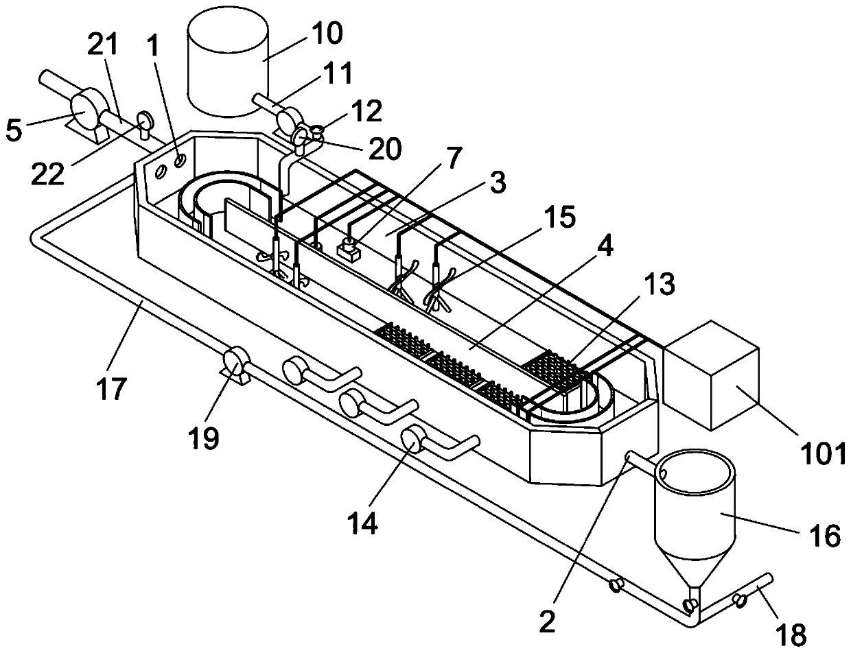
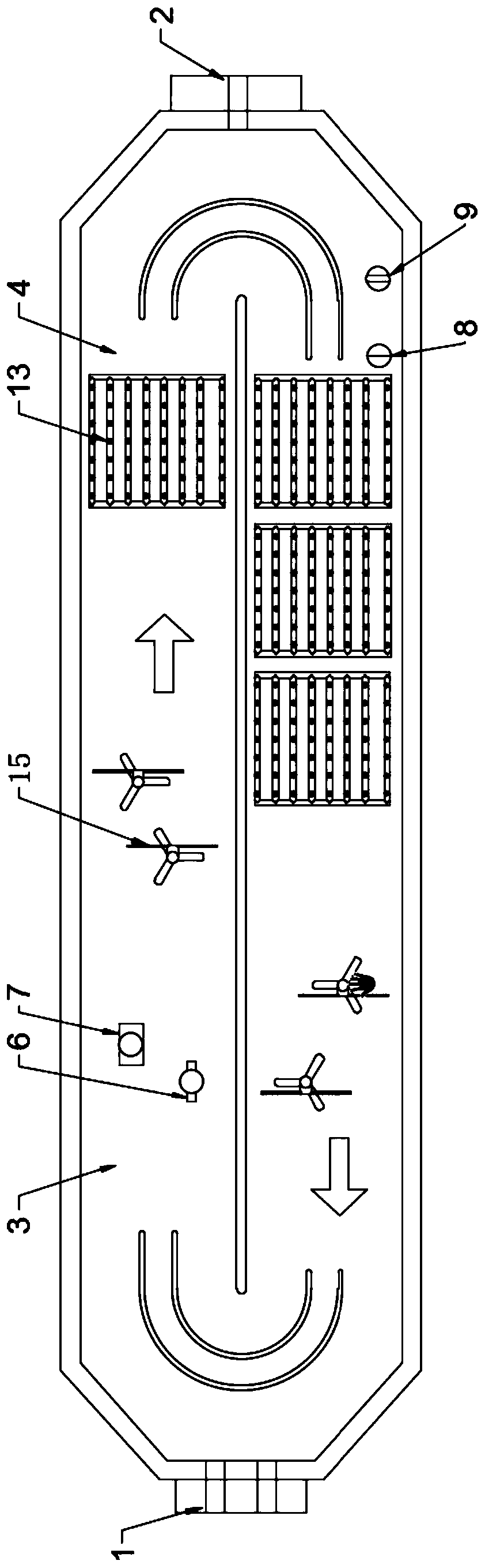
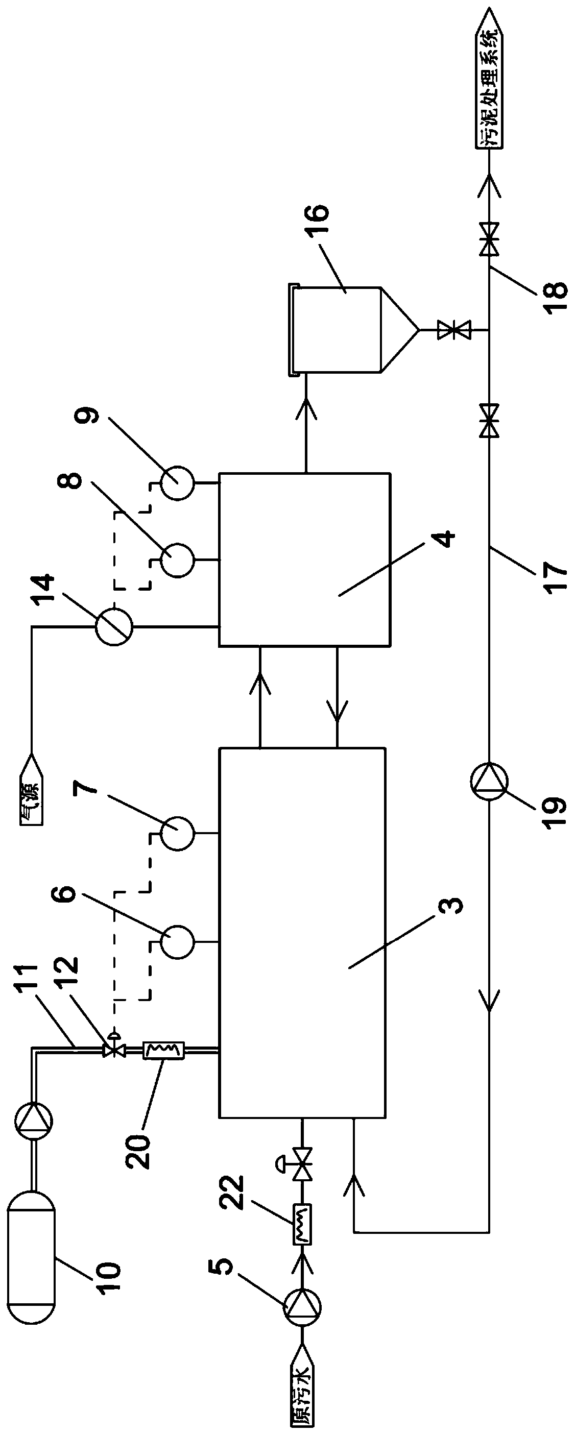
[0051] A system suitable for reducing consumption and improving efficiency of oxidation ditch biological denitrification, such as Figure 1 to Figure 3 As shown, it includes a biological reaction zone, which is divided into a non-aeration zone 3 near the front water inlet 1 side and an aeration zone 4 near the rear water out...


PUM


Abstract

The invention relates to the field of sewage treatment, in particular to a consumption reduction and efficiency improvement system and method suitable for oxidation ditch biological denitrification. The system is characterized by comprising a biological reaction zone which is divided into a non-aeration zone and an aeration zone, and a water inlet which is communicated with a water inlet pump through a sewage inlet pipe, wherein a sewage flow meter is arranged on the sewage inlet pipe, a nitrate nitrogen probe and an ORP probe are arranged in the non-aeration area, and an ammonia nitrogen probe and a DO probe are further arranged in the aeration area. The system further comprises a carbon source storage tank with a carbon source, the carbon source storage tank is communicated with the non-aeration area through a carbon source feeding pipe, and a flow control valve and a flow meter are sequentially arranged on the carbon source feeding pipe; and the water inlet pump, the sewage flow meter, the nitrate nitrogen probe, the ORP probe, the ammonia nitrogen probe, the DO probe, the flow regulating valve and the flow meter are respectively in communication connection with a PLC. Through the system and the method, the aeration rate and the carbon source addition amount during the biological denitrification process can be accurately controlled, and the balance between the nitrificationand the denitrification is controlled to improve the sewage treatment effect.

Description

【Technical field】 [0001] The invention belongs to the field of sewage treatment, and in particular relates to a system and method suitable for reducing consumption and improving efficiency of oxidation ditch biological denitrification. 【Background technique】 [0002] With the increasing environmental pollution, the country pays more and more attention to environmental protection. In recent years, all places have begun to implement the first-level A standard in the "Pollutant Discharge Standards for Urban Sewage Treatment Plants", mainly for TN (total nitrogen content ) are strictly controlled. In the face of increasing effluent standards, sewage plants around the world have adopted engineering measures to upgrade sewage standards to achieve effluent water quality to meet new discharge standards. However, with the increase of technological processes, the cost of per ton of water treatment has also increased. [0003] In the current sewage treatment process, oxidation ditch b...

Claims


Application Information

Patent Timeline
Patent Type & Authority Applications(China)
IPC IPC(8): C02F3/12C02F3/30C02F101/16
CPCC02F3/1257C02F3/302C02F2101/16Y02W10/10
Inventor 陆侨治吴益辉
Owner 浙江海牛环境科技股份有限公司
Why Eureka
Try Eureka