CFB boiler system capable of combusting waste gas and waste liquid in blending manner

A boiler and waste liquid technology, which is applied in the direction of burning fuels, incinerators, and combustion methods in a molten state, can solve the problems of high overall energy consumption of chemical plants, complex treatment systems, and environmental pollution, and achieves the realization of consumption, treatment and operation. Convenience, flexibility and economic benefits

Inactive Publication Date: 2019-11-22
HUANENG CLEAN ENERGY RES INST
View PDF10 Cites 2 Cited by
  • Summary
  • Abstract
  • Description
  • Claims
  • Application Information

AI Technical Summary

Problems solved by technology

Chemical plants will produce industrial waste gas and waste liquid during the production process. The use of torch combustion to burn the waste gas will not only cause energy waste, but also lead to high energy consumption of the chemical plant as a whole, and bring environmental pollution; waste liquid is a toxic and harmful substance, and a separate treatment system complex and costly
The consumption and treatment of chemical waste gas and waste liquid on the CFB boiler of the power station of the chemical plant can reduce the production cost and energy consumption of the chemical plant, realize the organic unity of energy saving, environmental protection, and economic benefits, and have good promotion and application value, but the existing The CFB boiler can't better realize the consumption and treatment of chemical waste gas and waste liquid

Method used


Image

  • CFB boiler system capable of combusting waste gas and waste liquid in blending manner

Examples


Embodiment Construction

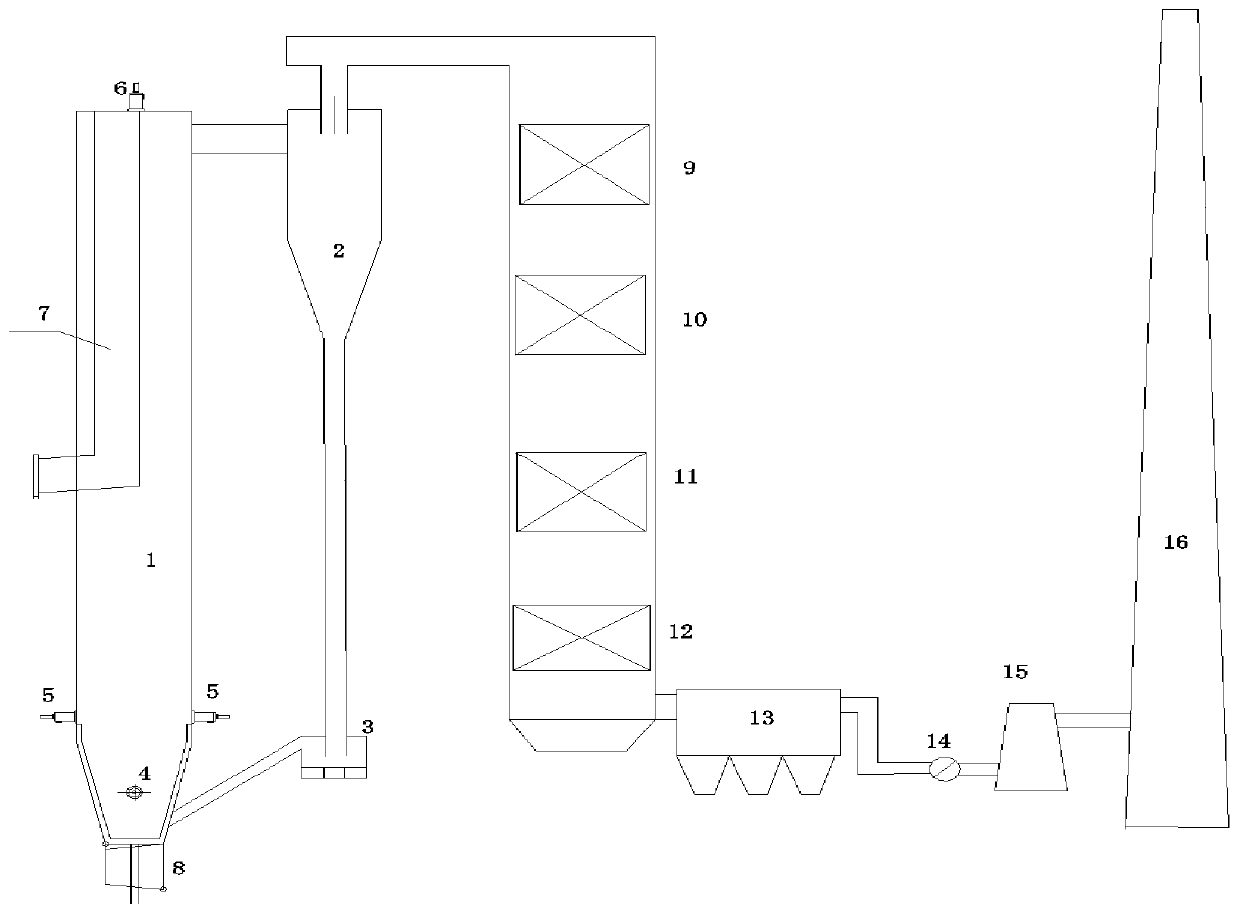
[0015] The present invention is described in further detail below in conjunction with accompanying drawing:

[0016] refer to figure 1 The CFB boiler system for burning waste gas and waste liquid according to the present invention includes a CFB boiler furnace 1, a boiler tail flue and a separator 2, the dense phase area on both sides of the CFB boiler furnace 1, the secondary tuyere area on the front and rear walls, and The top of the boiler is respectively provided with a first burner 4, a second burner 5 and a third burner 6; the flue gas outlet of the CFB boiler furnace 1 is connected to the inlet of the separator 2, and the flue gas outlet of the separator 2 is connected to the boiler The tail flue is connected, the bottom outlet of the separator 2 is connected with the inlet of the feeder 3, the outlet of the feeder 3 is connected with the inlet of the CFB boiler furnace 1, and the bottom of the CFB boiler furnace 1 is provided with an air distribution device 8 , wherei...


PUM


Abstract

The invention discloses a CFB boiler system capable of combusting waste gas and waste liquid in a blending manner. The CFB boiler system comprises a CFB boiler chamber, a boiler tail flue and a separator, wherein first combustors are respectively arranged on two side walls of a dense phase region of the CFB boiler chamber, second combustors are respectively arranged in secondary air nozzle regionson the front wall and rear wall of the CFB boiler chamber, and a third combustor is arranged at the top of the boiler; a flue gas outlet of the CFB boiler chamber communicates with an inlet of the separator; a flue gas outlet of the separator communicates with the boiler tail flue; an outlet in the bottom of the separator communicates with an inlet of a material returning machine; an outlet of the material returning machine communicates with an inlet of the CFB boiler chamber; and a wind distributing device is arranged at the bottom of the CFB boiler chamber. Through the adoption of the CFB boiler system disclosed by the invention, elimination treatment of the waste gas and the waste liquid can be better realized.

Description

technical field [0001] The invention belongs to the fields of thermal energy engineering and chemical industry, and relates to a CFB boiler system for burning waste gas and liquid. Background technique [0002] Circulating fluidized bed (CFB) boilers have the characteristics of wide fuel adaptability, good environmental protection, and strong load regulation capabilities, and have been widely used in my country's thermal power and chemical industries. Chemical plants will produce industrial waste gas and waste liquid during the production process. The use of torch combustion to burn the waste gas will not only cause energy waste, but also lead to high energy consumption of the chemical plant as a whole, and bring environmental pollution; waste liquid is a toxic and harmful substance, and a separate treatment system Complicated and costly. The consumption and treatment of chemical waste gas and waste liquid on the CFB boiler of the power station of the chemical plant can red...

Claims


Application Information

Patent Timeline
IPC IPC(8): F23C10/00F23C10/18F23C10/22F23G7/04F23G7/06
CPCF23C10/00F23C10/18F23C10/22F23C2206/10F23G7/04F23G7/06F23G2209/101F23G2209/14
Inventor 赵鹏勃李楠高洪培孙献斌时正海李力
Owner HUANENG CLEAN ENERGY RES INST
Why Eureka
Try Eureka