
Method for calibrating DC offset of radio frequency receiving circuit, electronic equipment, medium and device

A technology of DC offset and radio frequency reception, applied in the direction of electrical components, amplification control, transmission system, etc., can solve the problems of large chip area, poor DC offset calibration effect, loss of low-frequency signal, etc., and achieve the effect of DC offset calibration function

Active Publication Date: 2021-06-04
GUANGZHOU RUNXIN INFORMATION TECH
View PDF7 Cites 0 Cited by
  • Summary
  • Abstract
  • Description
  • Claims
  • Application Information

AI Technical Summary

Problems solved by technology

[0004] In order to overcome the deficiencies of the prior art, the purpose of the present invention is to provide a method for calibrating the DC offset of the radio frequency receiving circuit, which solves the problem that the existing DC offset calibration method needs to occupy a large chip area, consume low-frequency signals, and require a lot of auxiliary circuits. Problem with poor calibration

Method used


Image

  • Method for calibrating DC offset of radio frequency receiving circuit, electronic equipment, medium and device
  • Method for calibrating DC offset of radio frequency receiving circuit, electronic equipment, medium and device

Examples


Embodiment Construction

[0030] Below, the present invention will be further described in conjunction with the accompanying drawings and specific implementation methods. It should be noted that, under the premise of not conflicting, the various embodiments described below or the technical features can be combined arbitrarily to form new embodiments. .

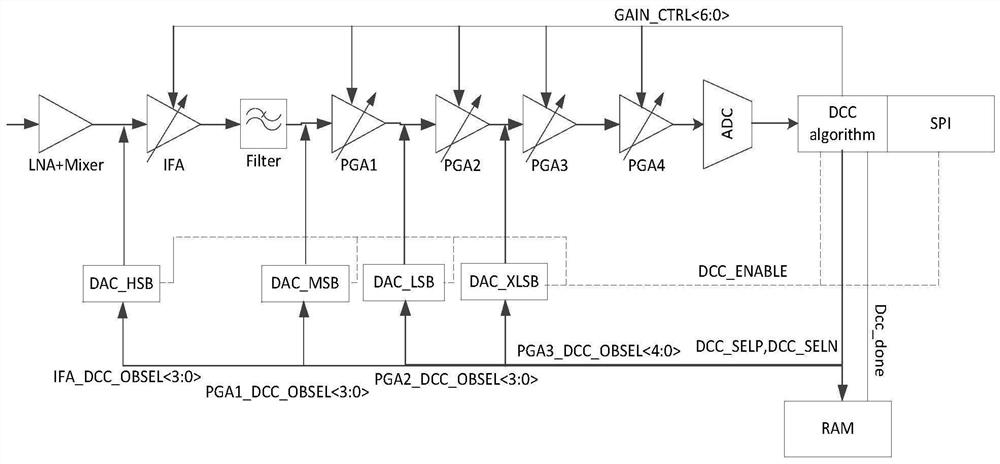
[0031] Such as figure 1 As shown, the DC offset calibration device of the radio frequency receiving circuit of the present invention is applied to the receiver circuit, wherein, LNA+Mixer is the radio frequency front end in the receiver chain, and IFA (intermediate frequency amplifier), FILTER, PGA1~PGA4 are the receiver chain IF circuit, IFA is an intermediate frequency amplifier, FILTER is a filter, PGA is a programmable gain amplifier, and ADC is a receiver analog-to-digital converter. Each module of the receiver link will generate a DC offset, which is then amplified by the gain of the subsequent stage. For example, the DC offset generated by the ...


PUM


Abstract

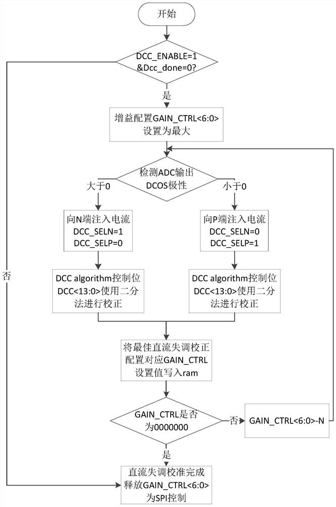
The invention provides a method for calibrating a DC offset of a radio frequency receiving circuit, comprising the steps of: configuring gain, detecting signal polarity, retrieving signal value, storing data, and cyclically calibrating. The invention relates to a device for calibrating DC offset of a radio frequency receiving circuit. The invention also relates to electronic equipment and a readable storage medium, which are used for implementing the method for calibrating the DC offset of the radio frequency receiving circuit. Combined with the receiving channel, the present invention can better realize the DC offset calibration function with only a few auxiliary circuits, does not need to occupy a large chip area, does not lose low-frequency signals, can adapt to the situation of multi-stage operational amplifiers, and adopts hierarchical processing In this way, the DC offset of each stage of op amp is calibrated separately, which prevents the intermediate nodes of the signal chain from being saturated before the DC offset is cancelled. The DC offset calibration effect is good, the size of the DC offset can be quantified, and the fault tolerance is good.

Description

technical field [0001] The invention relates to the technical field of automatic control of a radio frequency receiving circuit, in particular to a method for calibrating a DC offset of a radio frequency receiving circuit, electronic equipment, a medium and a device. Background technique [0002] In the field of modern wireless communication, low-IF and zero-IF receivers have great advantages in low power consumption and high integration, because zero-IF receivers only need one frequency conversion, so the structure is simpler, so zero-IF systems are becoming more and more popular. More and more are used in today's wireless devices. But on the other hand, due to non-ideal factors such as the randomness of the device during production and the leakage of the local oscillator, the DC offset generated by the positive and negative terminals of the differential signal is gradually amplified by the gain stage, which makes the DC operating point of the receiver shift or even saturat...

Claims


Application Information

Patent Timeline
Patent Type & Authority Patents(China)
IPC IPC(8): H04B1/40H03G3/20
CPCH03G3/20H04B1/40
Inventor 贺黉胤王日炎许智宁郝强宇周伶俐
Owner GUANGZHOU RUNXIN INFORMATION TECH
Learn More