Medical transferring bed

A transfer bed and mobile bed board technology, applied in medical transportation, hospital beds, medical science, etc., can solve the problems of prone to failure, easy to move left and right on the cloth surface, difficult to clean, etc.

Pending Publication Date: 2019-12-03
沛霖医疗技术(广州)有限公司
View PDF2 Cites 14 Cited by
  • Summary
  • Abstract
  • Description
  • Claims
  • Application Information

AI Technical Summary

Problems solved by technology

[0005] The above-mentioned transmission belt (Chinese patent 98205338.X) or the upper moving cloth (Chinese patent 200610052776.3) are all driven by the rotation of the rubber roller, thereby driving the transmission belt or the upper moving cloth set on the rubber roller to move laterally back and forth to approach or move away from For the operating table / sickness bed, since the transmission of the cloth surface requires a certain tension force, it is necessary to adjust the tension degree of the cloth surface after a long time; the cloth surface must be replaced when it is stretched to a certain extent, otherwise the guardrails on both sides of the vehicle body will be closed. No; the cloth surface of this structure is easy to move left and right, and needs to be debugged; in addition, the setting of rubber rollers will also cause many problems, such as the attached manual of "medical patient transfer vehicle" disclosed in Chinese patent 200610052776.3 Figure 16 The gap between the middle rubber roller 15 and the end joint seat body 16 is easy to get the clothes into the rubber roller, and may also pinch the hair in the process of transferring the patient; moreover, the rubber roller will also be aging, so it is necessary to replace the rubber roller and re-adjust the equipment operating status etc.
[0006] As in the transmission mechanism of Chinese patent 200610052776.3, a clutch is used for transmission. The clutch adopts a mechanical control structure in which two clutch gears are engaged and separated. The disadvantage is that the design structure is complex and prone to failure; When the two teeth of a clutch gear are not coordinated, the combination will not be smooth, and when separation is required, when the two teeth mesh, there will be separation resistance, resulting in a large difference in movement and positioning, and the transfer of the patient cannot be completed satisfactorily.
[0007] In addition, the transmission belt or the up and down moving cloth is a circular and closed conveying cloth, which is in direct contact with the patient's body and is the main component used to directly pick up and send the patient; due to the needs of medical hygiene, the transmission belt or the up and down movement Disinfection of the cloth surface can easily lead to cracking of the cloth surface interface, and the structural strength is not enough
[0008] 2. Health problems
[0009] The transmission belt or the up and down moving cloth is in direct contact with the patient's body, and the cloth surface is easy to be dirty, including blood stains, human exudate, therapeutic drug exudate and other stains, because the transmission belt or the up and down moving cloth are The circular closed conveying cloth is difficult to clean when hidden in the machine, and it is also difficult to replace the conveying cloth. The workload of dismantling and assembling a replacement conveying cloth is no less than the workload of assembling a new machine. Therefore, the cloth surface is dirty. can't solve
[0010] 3. Security issues
If the patient is already on the transfer bed and presses the button inserted into the bed by mistake, the patient will bump into the end connector base 16 or even fall across the end connector base 16 to the transfer bed frame, resulting in medical accidents

Method used


Image

  • Medical transferring bed
  • Medical transferring bed
  • Medical transferring bed

Examples


Embodiment 1

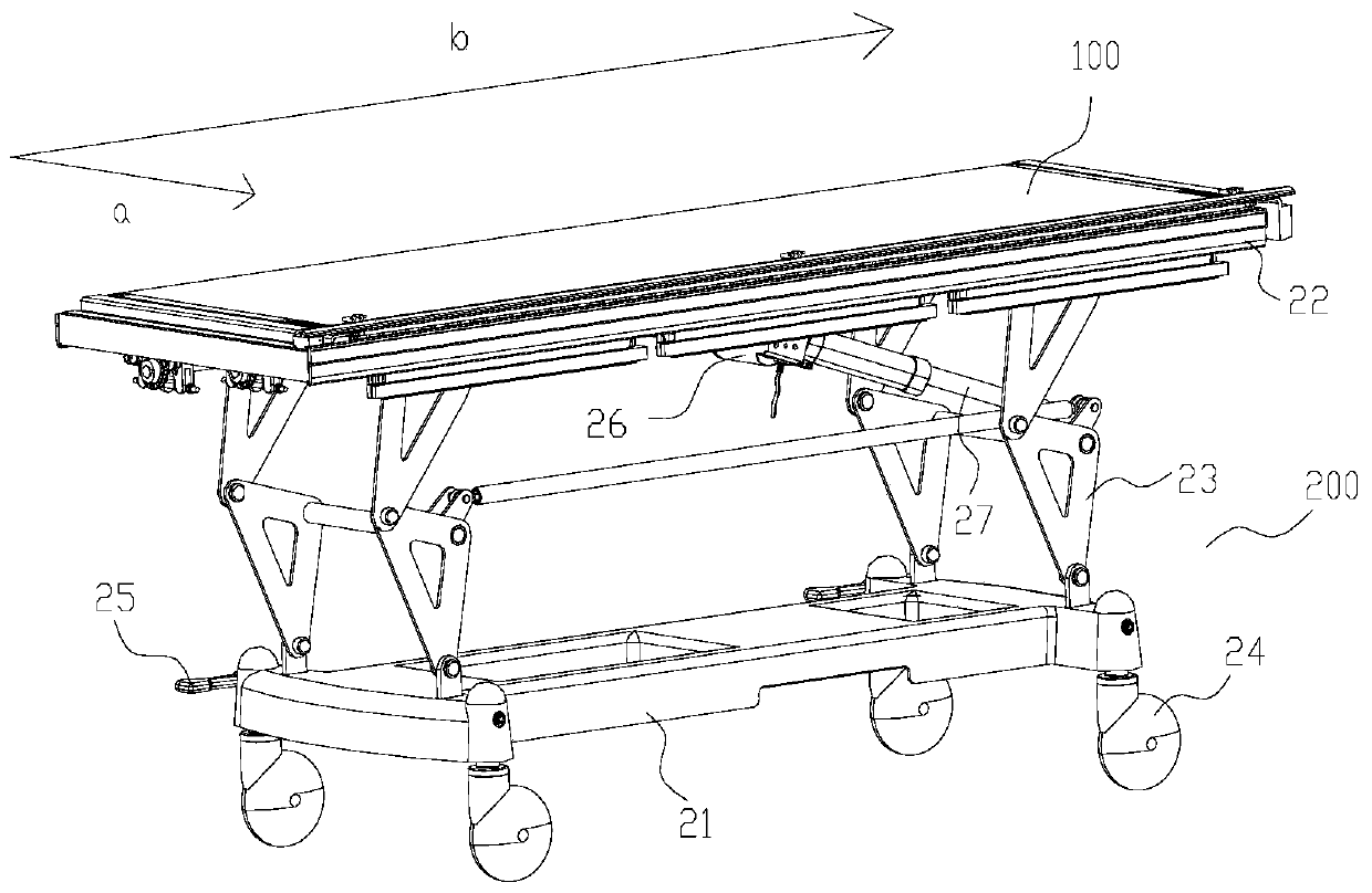
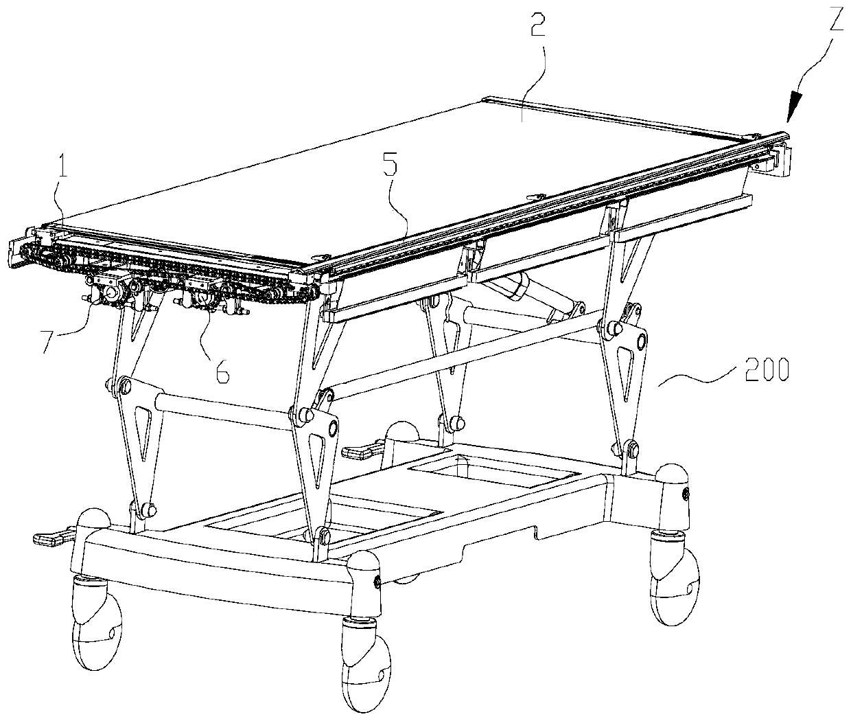
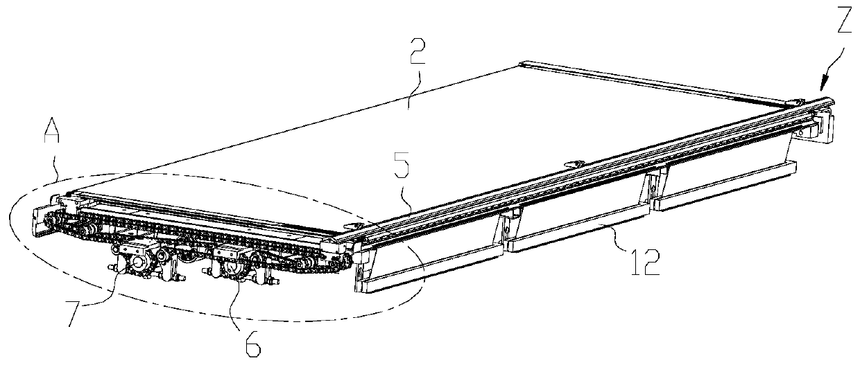
[0053] Embodiment 1 is one of preferred embodiments of the present invention, as Figure 1-23 As shown, the medical transfer bed of this embodiment includes a car body 200 with a lifting mechanism and universal casters installed, and a mobile bed board mechanism 100 for laterally moving patients; the mobile bed board mechanism is installed on the vehicle frame of the car body 22 on. In this embodiment, the moving direction of moving the bed board mechanism to stretch back and forth to pick up and drop off the patient is the horizontal direction, such as figure 1 The a direction shown; on the same plane, the vertical direction is the direction perpendicular to each other in the horizontal movement direction, such as figure 1 The b direction shown; figure 1 The mobile bed board mechanism is installed on the car body without telescopic operation, which is the normal state of the medical transfer bed; the mobile bed board mechanism extends forward to be the front, and the mob...

Embodiment 2

[0077] Compared with Example 1, the difference between the medical transfer bed in Example 2 lies in the locking bar driving mechanism. In this embodiment, the locking bar driving mechanism adopts a ratchet, a structure similar to the principle of a ratchet, a brake mechanism, or an electromagnetic device. Wait for a kind of in existing locking mechanism. When locking mechanisms such as ratchets or electromagnetic devices are released (that is, the patient is loaded on the upper moving plate), since the patient is pressed on the upper moving cloth, the friction force between the upper moving cloth and the upper moving plate is large enough to overcome the passive movement of the lower moving cloth. The resulting friction causes the upper moving cloth to remain relatively stationary with the patient and the upper moving plate.

[0078] The working process of the medical transfer bed in the preferred embodiment of the present invention:

[0079] like Figure 22-23 As shown, the ...

Embodiment 3

[0086] In view of the conveying cloth in which the upper and lower moving cloths in the prior art are circularly closed, and once the upper and lower moving cloths are installed, they cannot be disassembled and replaced with new moving cloths, but can only be sterilized by alcohol. Therefore, if the disinfection is not enough, it is easy to cause crossover. Infection, it can be seen that the moving cloth of the existing medical transfer bed cannot be disassembled and cleaned, and it is difficult to achieve the purpose of completely preventing infection. Therefore, this embodiment 3 provides a medical transfer bed that is easy to replace the moving cloth. infection purpose.

[0087] Specifically, compared with Example 1, the difference between the medical transfer bed of Example 3 is that the upper moving cloth is provided with a longitudinal opening; the two sides of the longitudinal opening of the upper moving cloth are respectively connected with rigid limit strips 11; A li...


PUM


Abstract

The invention discloses a medical transferring bed. The medical transferring bed comprises a vehicle body, and a moving bed board mechanism, wherein the moving bed board mechanism is mounted on a vehicle frame of the vehicle body; the moving bed board mechanism comprises an upper moving board, an upper moving cloth, a lower moving board, and a lower moving cloth; the lower moving board is arrangedbelow the upper moving board; the upper moving board and the lower moving board are in synchronous lateral movement forward or backward; the upper moving cloth is coated on the periphery of the uppermoving board; a locking strip is longitudinally fixed to the upper moving cloth; the locking strip is locked to the shuttling side of the upper moving cloth, or is moved along with the upper moving cloth after locking is released; the lower moving cloth is coated on the periphery of the lower moving board; two ends of the lower moving cloth are fixed to the vehicle frame of the vehicle body; andthe lower moving cloth is located on the shuttling side of the lower moving board. According to the medical transferring bed disclosed by the invention, the locking strip is arranged, so that a mannerof rotating a transmission cloth through driving rubber rollers in the prior art is replaced; and the structure of the moving bed board mechanism is simplified, no friction coefficient requirement ofmoving cloths is generated, the moving resistance is lower, and the consumed power is lower.

Description

technical field [0001] The invention relates to a transport tool technology for loading and unloading patients, in particular to a medical patient transfer bed suitable for transporting postoperative patients in a hospital or transporting patients who are prone to re-injury during the transport process. Background technique [0002] At present, the medical transfer bed is used to move and transfer patients with inconvenient mobility before and after surgery, from the hospital bed to the transfer bed, and then from the transfer bed to the operating table or the equipment that needs examination / treatment, or reverse transfer. Especially for patients with wounds or patients who have undergone severe spine, cervical spine, and thoracic spine operations, the birth of the medical transfer bed reduces the labor intensity of the medical staff and avoids the possibility of bringing the patient several times during the transfer period before and after the operation. The secondary inju...

Claims


Application Information

Patent Timeline
Patent Type & Authority Applications(China)
IPC IPC(8): A61G1/02A61G1/04A61G7/14
CPCA61G1/0281A61G1/0287A61G1/04A61G7/103
Inventor 不公告发明人
Owner 沛霖医疗技术(广州)有限公司
Why Eureka
Try Eureka