Landfill leachate graphene integrated purification system and process

A landfill leachate and purification system technology, applied in the field of landfill leachate graphene integrated purification system, can solve the problems of long time consumption, low efficiency, and difficulty in popularization and use

Inactive Publication Date: 2019-12-03
东莞市粤绿环保有限公司
View PDF5 Cites 7 Cited by
  • Summary
  • Abstract
  • Description
  • Claims
  • Application Information

AI Technical Summary

Problems solved by technology

[0003] There are various problems in the existing domestic waste leachate wastewater treatment equipment or process, and the water quality after purification cannot meet the discharge standards
For example: Regulating tank plus surface aeration and stripping treatment, low efficiency, long time-consuming, residual ammonia pollutes the air, and only 68% nitrogen nitrogen removal rate and 76% COD removal rate (Wang Zongping, Tao Tao, Yuan Juxin, etc. . Landfill leachate pretreatment - ammonia stripping [J]. Water Supply and Drainage, 2001 (6), 15-19); electrolytic oxidation method consumes a lot of energy, the precious metal catalyst used is expensive, and equipment maintenance is relatively difficult (Li Ming, Yang Yong, Ji Min, etc. Experimental Research on Removal of Ammonia Nitrogen in Landfill Leachate by Catalytic Electrolysis[J]. Journal of Lanzhou Jiaotong University, 2007,26(3):35-37); UV / O 3 The investment and operating costs of the leachate treatment method are relatively high, and it is difficult to popularize and use them.

Method used


Image

  • Landfill leachate graphene integrated purification system and process

Examples


Embodiment 1

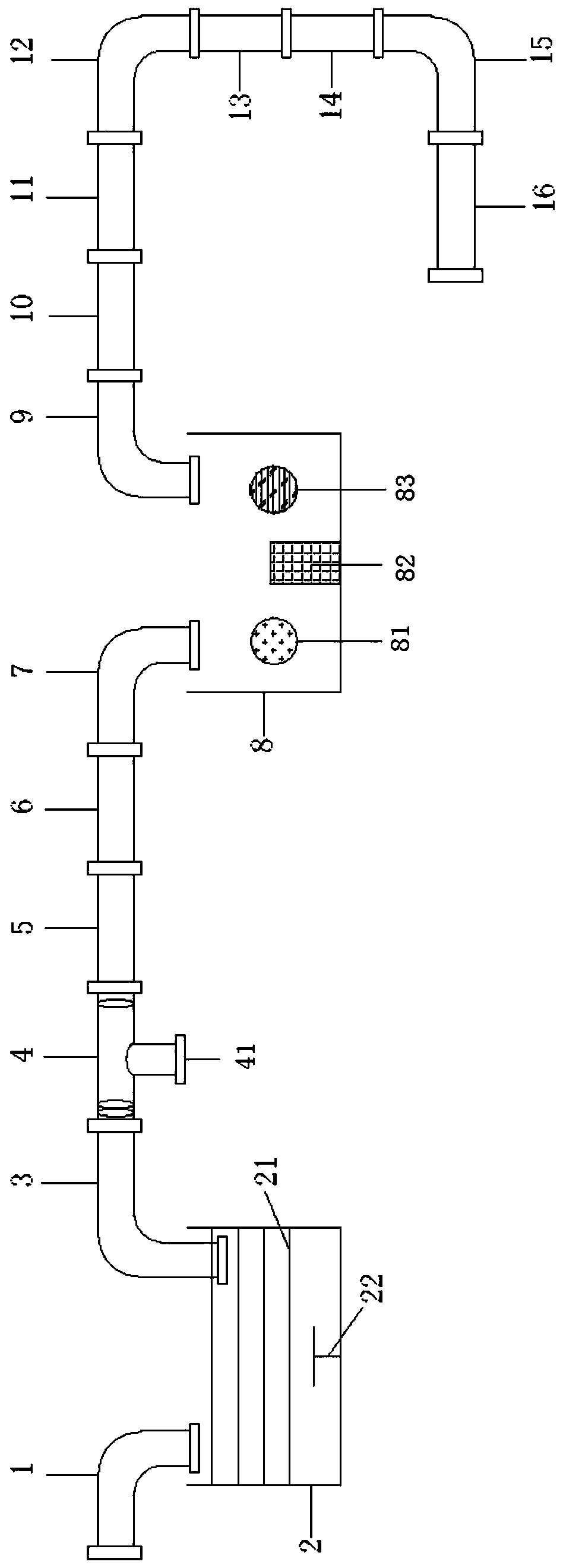
[0051] Such as figure 1 As shown, the leachate from domestic waste landfills, domestic waste dumps and other places is collected by the leachate collection valve and then transported into the anaerobic tank 2 (including the aeration port) by the permeate delivery pipe 1. The anaerobic tank 2 A multi-layer porous support 21 is built in, with a diameter of 2 mm, and is located above the stirring device 22. A pre-cultured autotrophic ammonia oxidation biofilm is placed on the support 21 in advance. The pH in the anaerobic tank 2 is controlled at 7.5, the temperature is 30℃, and the anaerobic environment is adjusted in time ( 2 And other harmless gases.

[0052] The leachate, which has been pre-removed of ammonia nitrogen and other pollutants through the anaerobic tank 2, is transported to the multi-stage filter device 4 by the delivery pipe 3 (pre-filtering screen is set at the bottom, and the screen has 16 meshes to remove most of the suspended solids). It is further filtered to r...

Embodiment 2

[0072] The difference between this embodiment and embodiment 1 is:

[0073] 1. The pore size of the multilayer porous support 21 built into the anaerobic tank 2 is 3 mm, the pH in the anaerobic tank 2 is controlled at 7.6, and the temperature is 28°C.

[0074] 2. The mesh number of the pre-filter screen located between the anaerobic tank 2 and the multi-stage filter device 4 is 12, the mesh number of the first-stage graphene enhanced filter is 12, and the mesh of the second-stage graphene enhanced filter is The number is 20, the mesh of the third-level graphene-enhanced filter is 40, the material of the first, second, and third-level graphene-enhanced filters is polypropylene, and the amount of graphene added is 2.0%.

[0075] 3. The graphene reinforced diatom ceramic material is wrapped with 20 mesh glass fiber cloth.

[0076] 4. The material of the graphene photocatalytic degradation device 6 is transparent ceramic.

[0077] 5. The size of the multiple purification tank 8 is length, ...

Embodiment 3

[0087] The difference between this embodiment and embodiment 1 is:

[0088] 1.The pore size of the multi-layer porous scaffold built into the anaerobic tank 2 is 5mm.

[0089] 2. The mesh number of the pre-filter screen located between the anaerobic tank 2 and the multi-stage filter device 4 is 8, the mesh number of the first-stage graphene enhanced filter is 14, and the mesh of the second-stage graphene enhanced filter The number is 18, the mesh of the third-level graphene-enhanced filter is 40, the material of the first, second, and third-level graphene-enhanced filters are all polyether ether ketone, and the amount of graphene added is 1.5%.

[0090] 3. The graphene reinforced diatom ceramic material is wrapped with 30 mesh glass fiber cloth.

[0091] 4. The material of the graphene photocatalytic degradation device 6 is transparent ceramics, and the graphene photocatalytic degradation agent is phosphotungstic acid / graphene oxide.

[0092] 5. The size of multiple purification tank 8...


PUM

PropertyMeasurementUnit
sizeaaaaaaaaaa
particle diameteraaaaaaaaaa
sizeaaaaaaaaaa

Abstract

The invention provides a landfill leachate graphene integrated purification system. The system comprises a landfill leachate collection and transportation apparatus, and further comprises an anaerobictank, a multi-stage filtering apparatus, a multi-stage graphene water purification apparatus, a graphene photo-catalytic degradation apparatus, a multiple purification tank, a multi-stage graphene sterilization apparatus, and a graphene ceramic water purification apparatus. The invention also provides a purification process using the purification system. The system is used to purify landfill leachate, and can achieve effects such as thorough purification, high efficiency, and low cost.

Description

Technical field [0001] The invention relates to the field of landfill leachate purification, in particular to a landfill leachate graphene integrated purification system and process. Background technique [0002] Landfill leachate generally refers to the water contained in the garbage itself, the rain, snow, and other water entering the landfill, deducting the saturated water holding capacity of the garbage and the overburden, and going through the garbage layer and the overburden. The formation of a high-concentration organic wastewater also includes the water leaked from the garbage accumulation site. Domestic waste leachate specifically refers to high-concentration organic waste water in the leakage of domestic waste landfills and accumulation sites, which is highly polluting waste water that is strictly prohibited by the state for direct discharge. [0003] The existing domestic garbage leachate wastewater treatment equipment or process has various problems, and the water qual...

Claims


Application Information

Patent Timeline
Patent Type & Authority Applications(China)
IPC IPC(8): C02F9/14C02F103/06
CPCC02F1/001C02F1/283C02F1/30C02F1/50C02F1/78C02F3/28C02F9/00C02F2103/06C02F2301/08
Inventor 夏玉峰程金生程旭谢梓欣程颖植键莹
Owner 东莞市粤绿环保有限公司
Why Eureka
Try Eureka