Watercourse sluice gate with stratified water intake function and operation method thereof

A layered water intake and gate technology, applied in water conservancy projects, sea area projects, water supply devices, etc., can solve the problems that ordinary gates cannot be realized, and achieve good landscape effects and simple structures

Pending Publication Date: 2019-12-10
YANGZHOU UNIV
View PDF0 Cites 0 Cited by
  • Summary
  • Abstract
  • Description
  • Claims
  • Application Information

AI Technical Summary

Problems solved by technology

The traditional single-layer water intake method will cause the temperature of the water discharged from the reservoir to be lower than the natural water temperature of the river in summer and higher than the natural water temperature of the river in winter. The low temperature water discharged from the reservoir will have a significant adverse effect on the reproduction and growth of aquatic organisms in the downstream river.
[0003] At present, in some agricultural irrigation projects, it is strictly required to take warm surface water for agricultural irrigation to increase crop yields, but ordinary gates cannot fulfill this functional requirement

Method used


Image

  • Watercourse sluice gate with stratified water intake function and operation method thereof
  • Watercourse sluice gate with stratified water intake function and operation method thereof
  • Watercourse sluice gate with stratified water intake function and operation method thereof

Examples


Embodiment Construction

[0040] Embodiments of the present invention will be further described below in conjunction with the accompanying drawings.

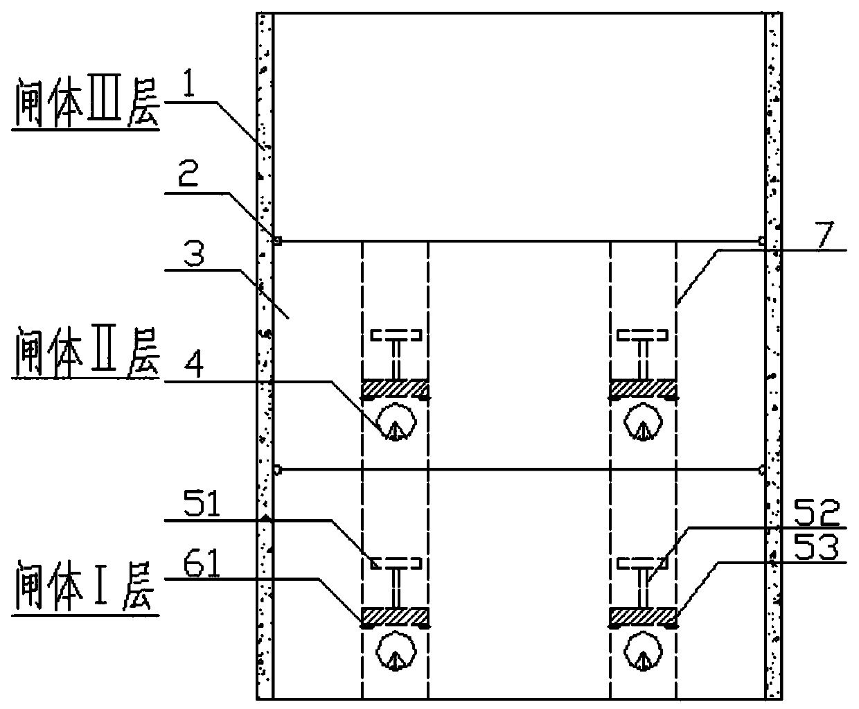
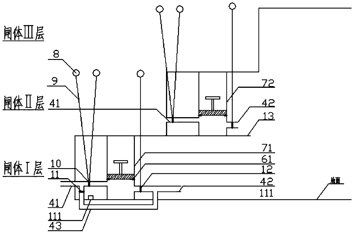
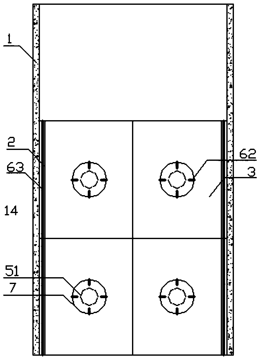
[0041] Such as Figure 1 to Figure 11-4 As shown, a river gate with layered water intake function includes: gate pier 1, rotating shaft 2, flap 3, pipeline 4, piston 5, limit iron block 6, water storage bucket 7, floating ball 8, rope 9, Water inlet pipeline liquid level control valve 10, electric valve 11, water outlet pipeline liquid level control valve 12, support plate 13, water stop 14.

[0042] The gate pier 1 is a reinforced concrete structure and is arranged on both sides of the river gate.

[0043] The river gate in this embodiment is stepped, and the overall structure is three layers, but not limited to three layers, and can be set as a multi-layer structure. initial state as figure 1 , 2 , each platform below the uppermost layer has three spaced steel plates in the vertical direction of water flow; the steel plate of the gate body of the low...


PUM


Abstract

The invention provides a watercourse sluice gate with a stratified water intake function thereof. The sluice gate comprises a plurality layers of platforms which form a step-like structure and are arranged in the water flowing direction. The platforms below the topmost platform are all of hollow structures. The top of each hollow structure is covered with turning plates. The turning plates are rotatably connected with the corresponding platforms. Each hollow structure is internally provided with water buckets with top openings. A piston is arranged in the middle of each water bucket. The top of each piston is provided with a push head used for pushing to the corresponding turning plate to rotate. The two sides of the bottom of each water bucket are connected with a water inlet pipe and a water outlet pipe correspondingly. Liquid level control valves are arranged in the water inlet pipes and the water outlet pipes. The bottoms of the water buckets of the bottommost platform are furtherprovided with underground pipes. Water inlets of the underground pipes communicate with water inlets of the water inlet pipes and are internally provided with electric valves. The turning plates can rotate up and down through the liquid level control valves according to the water level, and stratified water intake and surface water intake can be realized through internal water passing or top waterpassing of the watercourse sluice gate.

Description

technical field [0001] The invention relates to the field of water conservancy engineering equipment, in particular to a novel gate structure for water conservancy engineering, that is, a river gate with layered water intake function and its working method. Background technique [0002] The construction of the water conservancy project has a significant impact on the environment of the reservoir area and the downstream river course. The formation of the reservoir turned the original natural river with fast flow velocity and uniform water temperature into a relatively static large-scale water body. Affected by solar radiation, convective mixing and heat transfer, the vertical water temperature of the water body in the reservoir area appeared a climatic distribution, and the water temperature of the bottom water body was relatively low. The natural water temperature is low. The traditional single-layer water intake method will cause the temperature of the water discharged fro...

Claims


Application Information

Patent Timeline
Patent Type & Authority Applications(China)
IPC IPC(8): E02B8/00E02B8/04E03B3/04
CPCE02B8/00E02B8/04E02B8/045E03B3/04
Inventor 徐波孙晨光陆伟刚李占超夏辉张从从顾梦凡
Owner YANGZHOU UNIV
Why Eureka
Try Eureka