Pneumatic disconnection and dust removal device and method for distribution box

A technology of dust removal device and distribution box, which is applied in substation/power distribution device shell, power device inside switch, panel/switch station circuit device, etc., which can solve problems affecting physical and mental health, electric shock, shortening the service life of components, etc. , to avoid the injury of operators and guardians, the operation is completely reliable, and the effect of avoiding physical injury

Inactive Publication Date: 2020-09-25
程强
View PDF6 Cites 0 Cited by
  • Summary
  • Abstract
  • Description
  • Claims
  • Application Information

AI Technical Summary

Problems solved by technology

[0002] Electricity is the driving force of modern industry. In the process of electric power transmission, changing high voltage to low voltage is a common situation encountered by electric power departments. At present, the operation of changing high voltage to low voltage on the distribution box is mostly manual operation. The process is, a The operation should be monitored by more than two people. This is an important safety measure written into the operating procedures, otherwise it is not allowed to operate. In this way, the operation is not only troublesome, but also the operator will be affected by electromagnetic interference and affect people's physical and mental health. , therefore, we invented a device for pneumatically disconnecting electricity
[0003] In addition, the wiring box also involves dust-proof issues: First, it is to prevent some exposed components in the cabinet from being covered by dust. If it is covered by dust and then absorbs moisture in the air, it will corrode some exposed components. A long time may lead to insulation reduction, short circuit, grounding and other faults, and may even lead to the risk of electric shock; 2. Excessive dust coverage will lead to excessive electrostatic current in the case of humid air, which will also cause it to be damaged during operation. The danger of electric shock, and excessive dust coverage will cause corrosion to the components of the box, and will greatly shorten the service life of the components
This patented technology uses ultrasonic vibration components to cooperate with air to remove dust. This operation requires power-off operation of the distribution box, and dust removal is not carried out when the power is charged, which affects the power supply.

Method used


Image

  • Pneumatic disconnection and dust removal device and method for distribution box
  • Pneumatic disconnection and dust removal device and method for distribution box
  • Pneumatic disconnection and dust removal device and method for distribution box

Examples


Embodiment 1

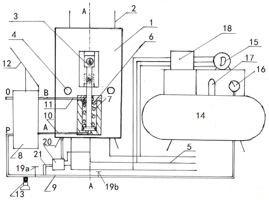
[0041] Embodiment 1, with reference to attached Figure 1-3 , a pneumatic disconnection and dust removal device for a distribution box mentioned in the present invention, its technical solution is: including a distribution box main body 1, a high-voltage household line 2, an electric key 3, an electric key control cylinder 6, and a control reversing air valve 8. Remote air pipeline 9, reversing handle 12, external start-up interface 13, air compressor storage tank 14, air compressor 15, pressure relay 18, first stop valve 19a, second stop valve 19b, solenoid valve 20. Dust removal pipe 21, power terminal 22, power supply terminal 23, electric key fixing plate 24, power contact 25, fixing bolt 26, relay 27, fuse 28, transformer 29, high-voltage household line 2 connected to the distribution box The power terminal 22 in the inner cavity of the main body 1 is fixed on the inner wall of the main body 1 of the distribution box through the electric key fixing plate 24 and the insula...

Embodiment 2

[0057] Embodiment 2, another situation that the present invention runs into is:

[0058] Refer to attached Figure 10 , when the air compressor storage tank 14 or the air compressor 15 fails, the gas manual compression device can be connected through the external starting interface 13, and the gas manual compression device includes a gas exchange joint a, a sealed cylinder liner b, and a sealed piston c , working lead screw d, force nut e, connecting lock cap f, fixing screw g, connecting pin h, locking pin i, transition nut j and hand wheel k, one end of the sealed cylinder b is movably connected to the gas The exchange joint a, the other end is connected to the force nut e through the locking pin i, the center of the gas exchange joint a is provided with a vent nozzle, and is movably connected to the external starting interface 13; the force force nut e There is a working screw d in the center, the outer end of the working screw d is provided with a hand wheel k, the inner ...

Embodiment 3

[0059] Embodiment 3, the difference between the present invention and embodiment 1 is:

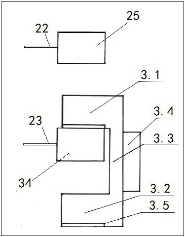
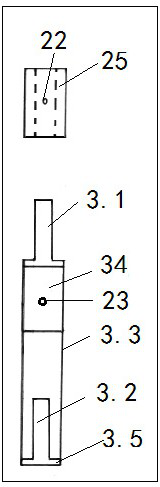
[0060] There is a switch execution block 3.4 on the outside of the bridge connector 3.3 on the side of the electric key. The switch execution block 3.4 is directly connected and fixed with the connecting rod of the electric key control cylinder 6. The electric key control cylinder 6 drives the connection block 35 to move up and down, driving the bridge connector. 3.3 Move up and down, so that the upper contact 3.1 of the electric key and the lower contact 3.2 of the electric key are inserted into the power contact 25 and the power supply contact 34 to form a power circuit, or removed from the power contact 25 and the power supply contact 34 to form a power-off state.

[0061] The switch execution block 3.4 here is provided with a plurality of connecting screw holes 3.6, so that the electric key control cylinder 6 can be installed according to the position of the distribution box, and direct...


PUM


Abstract

The invention relates to a device and method for pneumatic disconnection and dust removal for a distribution box. Its technical solution is: the outside of the electric key is connected to the electric key control cylinder through a connecting rod, the electric key control cylinder is connected to the control reversing air valve through the closed air pipeline, and the control reversing air valve is connected to the air cylinder through the remote air transmission pipeline. Compressor air storage tank, and a cut-off valve is provided on the remote gas transmission pipeline, the air compressor air storage tank is connected to the air compressor, and the air compressor is used to press the control reversing air valve to realize the switch of the electric key; the distribution The lower side of the main body of the electric box is provided with a dust removal pipe, and a solenoid valve is arranged on the dust removal pipe, and is connected to the gas storage tank of the air compressor. The beneficial effect is: the present invention uses gas as the power, which can avoid or reduce the interference of electromagnetic field on human physiology, and through the induction circuit composed of dust attracting capacitor, gas circuit opening coil and rectifier, automatic induction and dust removal become possible, avoiding The physical damage caused by manual dust removal is avoided.

Description

technical field [0001] The invention relates to a distribution box and a method for electric power, in particular to a device and method for pneumatic disconnection and dust removal for a distribution box. Background technique [0002] Electricity is the driving force of modern industry. In the process of electric power transmission, changing high voltage to low voltage is a common situation encountered by electric power departments. At present, the operation of changing high voltage to low voltage on the distribution box is mostly manual operation. The process is, a The operation should be monitored by more than two people. This is an important safety measure written into the operating procedures, otherwise it is not allowed to operate. In this way, the operation is not only troublesome, but also the operator will be affected by electromagnetic interference and affect people's physical and mental health. , Therefore, we have invented the device of pneumatically disconnectin...

Claims


Application Information

Patent Timeline
Patent Type & Authority Patents(China)
IPC IPC(8): H02B1/46H02B1/48H02B1/28H02B1/24H01H3/24
CPCH02B1/46H02B1/48H02B1/28H02B1/20Y02B90/20
Inventor 程强徐丽何瑞孙文波杜海涛
Owner 程强
Why Eureka
Try Eureka