Predictive current control method for cascaded H-bridge inverter permanent magnet motor system

A technology for predicting current and permanent magnet motors, which is used in the fields of high-voltage and high-power AC motor variable frequency speed regulation, multi-level inverters and motor drive control. It can solve the problem that the reference voltage vector is no longer accurate, sacrificing system dynamic performance, reducing problems such as the amount of calculation, to achieve the effect of improving the current dynamic characteristics, reducing the amount of calculation, and low common-mode voltage

Active Publication Date: 2019-12-10
TIANJIN UNIV
View PDF6 Cites 12 Cited by
  • Summary
  • Abstract
  • Description
  • Claims
  • Application Information

AI Technical Summary

Problems solved by technology

However, for the cascaded H-bridge multilevel inverter-permanent magnet synchronous motor system (CHB-PMSM), with the increase of cascaded units and the increase of the number of levels, the number of space voltage vectors and the number of switch states are proportional to each other. The exponential form increases. For example, the number of switching states of the three-phase five-level cascaded H-bridge inverter is (4^6=4096), and it is obviously difficult to realize the system output under all switching states using the traditional model predictive control method. of
[0004] Some researchers have proposed a variety of improved methods to reduce the amount of calculation, one of which is the model prediction method that only considers the adjacent vector (MPC-a

Method used


Image

  • Predictive current control method for cascaded H-bridge inverter permanent magnet motor system
  • Predictive current control method for cascaded H-bridge inverter permanent magnet motor system
  • Predictive current control method for cascaded H-bridge inverter permanent magnet motor system

Examples


Embodiment Construction

[0037] In order to make the purpose, technical solution and advantages of the present invention clearer, the implementation manners of the present invention will be further described in detail below.

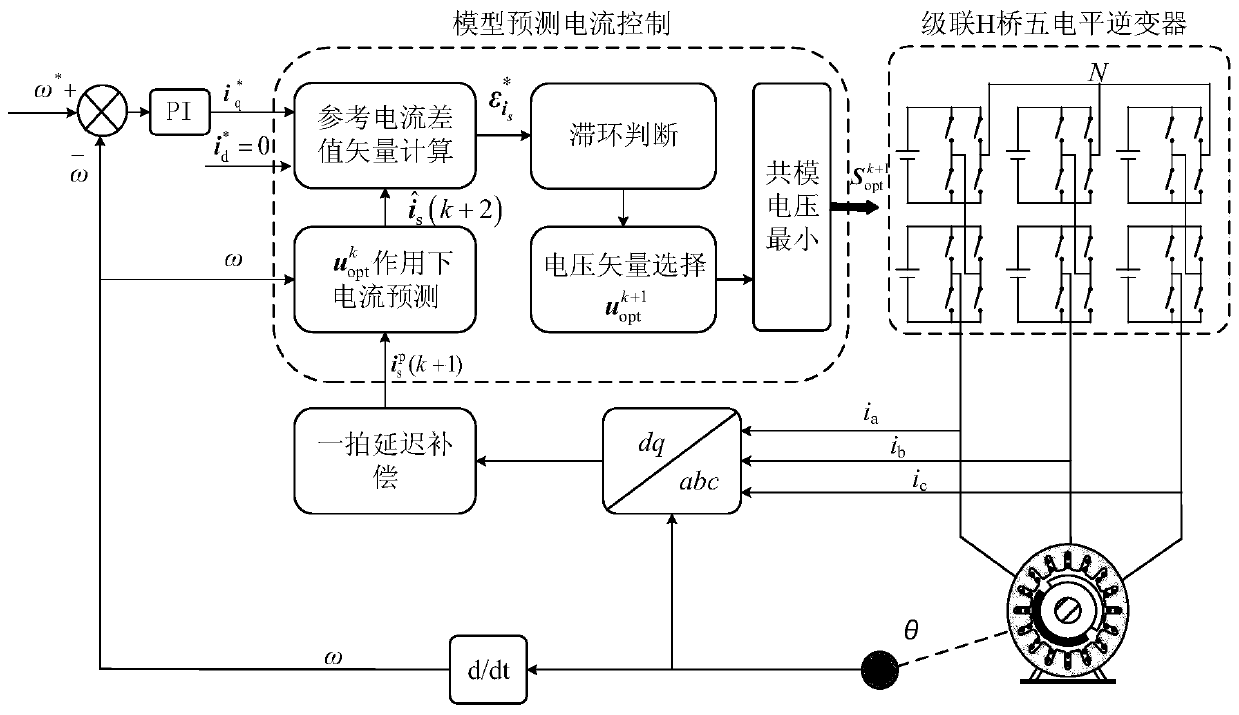
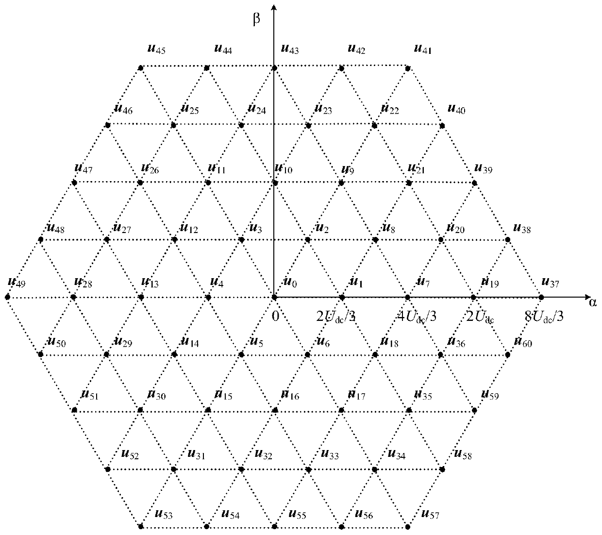
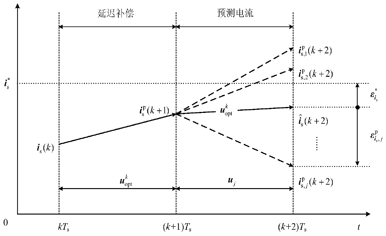
[0038] With the increase of cascaded units, the traditional model predictive control method has problems such as too many voltage space vectors and redundant switch states, complex selection of switch states, and a large amount of calculation. The predicted current trajectory under the continuous action of the vector is calculated to obtain the current error vector; at the same time, the hysteresis control is introduced, and the hysteresis interval is judged according to the magnitude of the current error vector, and the optimal voltage vector is selected according to the phase angle of the current error vector. , so as to determine the optimal voltage vector; in order to reduce the complexity of common-mode voltage and redundant state selection, the optimal voltage vector is gen...


PUM


Abstract

The invention discloses a predictive current control method for a cascaded H-bridge inverter permanent magnet motor system. The method comprises the steps: connecting a surface-mounted permanent magnet synchronous motor to the three-phase output side of a cascaded H-bridge multilevel inverter, and establishing a discretization mathematic model in a complex vector form under a d-q coordinate system; acquiring a predicted current vector of a voltage vector actually acting in a kth control period under the action of a (k+1)th control period based on the model; constructing a value function according to the relationship between the current vector and the voltage vector increment; and determining the hysteresis width and the increment of an optimal voltage vector according to the amplitude andphase angle of a current error vector, and determining an optimal voltage vector of the (k+1)th control period according to an optimal voltage vector under the action of the kth control period. The prediction frequency and the value function optimization frequency can be reduced, the complexity of a multi-level model predictive control algorithm can be greatly reduced, and the method has better dynamic and stable performances.

Description

technical field [0001] The present invention relates to the field of multilevel inverter and motor drive control, in particular to a predictive current control method for cascaded H-bridge inverter permanent magnet motor system, which can be applied to rail transit traction and ship propulsion systems Medium and high-voltage high-power AC motor frequency conversion and speed regulation field. Background technique [0002] In the field of medium and high-voltage high-power drives, due to the limitation of the withstand voltage and loss of a single power electronic device, two-level inverters have problems such as high dv / dt, high harmonic content, large switching losses of power devices, and serious electromagnetic interference. A series of problems limit its application. For this reason, multilevel inverters have attracted the attention of domestic and foreign researchers because of their unique advantages in high-voltage and high-power applications. As a representative mu...

Claims


Application Information

Patent Timeline
IPC IPC(8): H02P21/22H02P6/34
CPCH02P6/34H02P21/22
Inventor 史婷娜刘福顺姚欢王志强张国政
Owner TIANJIN UNIV
Why Eureka
Try Eureka