

Chain saw separation and connection device air-cooling device
An air-cooling device and clutch technology, applied in clutches, friction clutches, mechanical drive clutches, etc., can solve problems such as the decrease in the strength of the worm, the severe wear of the shoe block and the clutch housing, and the lack of products.
- Summary
- Abstract
- Description
- Claims
- Application Information
AI Technical Summary
Problems solved by technology
Method used
Image

Examples
Embodiment Construction
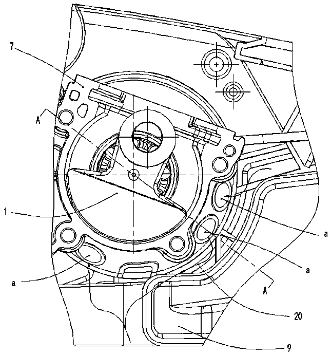
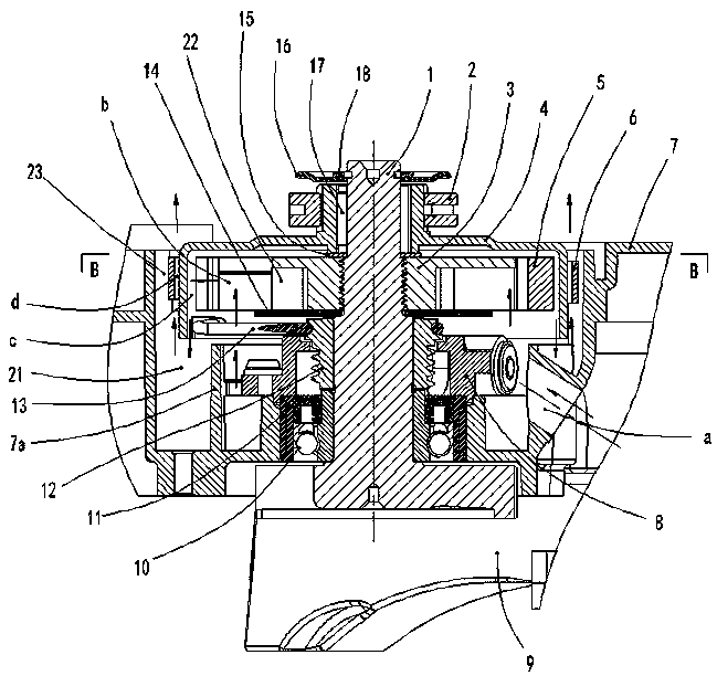
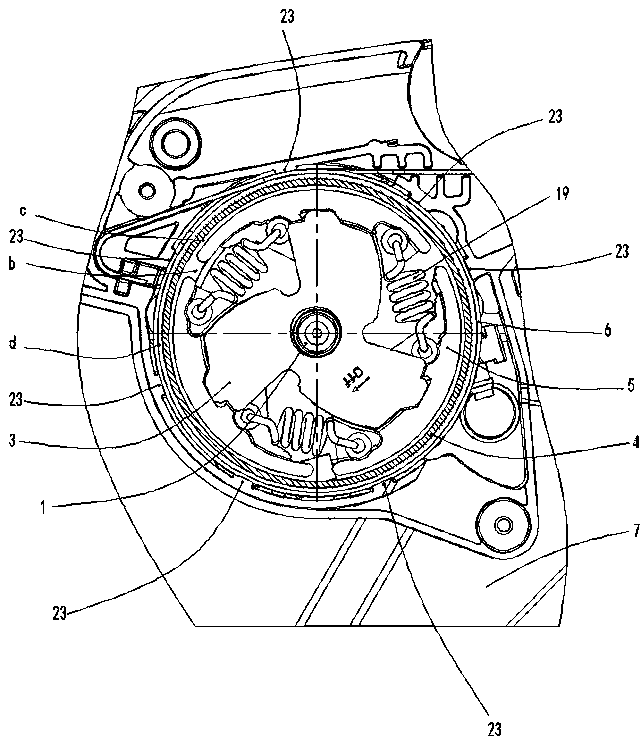
[0017] Figure 1 to Figure 5 As shown, the present invention creates a specific embodiment of a chainsaw clutch air-cooling device, which includes a right box 7, a right crank 1, a cage 3, a shoe 5, a clutch housing 4, a sprocket 2, and a brake band 6. The right crank 1 is rotatably installed on the clutch chamber of the right box 7 through the right box bearing 10 and the right box oil seal 11. The cage 3 is a star structure and fixed on the right crank 1. The flower of the clutch housing 4 The key sleeve is rotatably arranged on the right crank 1 through the needle bearing 17, the sprocket 2 is installed on the spline sleeve of the clutch housing 4, the brake band 6 is sleeved on the clutch housing 4, and the shoe block 5 is correspondingly arranged on the The cage 3 is connected to each other through the clutch spring 19, and is restricted inside by the outer cover of the clutch housing 4. There is a shoe gap b between adjacent shoes 5, and the clutch chamber of the right b...
PUM
 Abstract
Description
Claims
Application Information