Temperature rise monitoring device of power transmission line node based on induction electricity taking

A technology for inductive power acquisition and transmission lines, which is applied to battery circuit devices, circuit devices, measuring devices, etc., can solve problems such as failure to work normally, short life of temperature rise monitoring devices, etc., and achieve significant grid benefits and social and economic benefits, and improve Reliability and intelligence level, the effect of promoting automation

Inactive Publication Date: 2019-12-20
GUIZHOU POWER GRID CO LTD
View PDF5 Cites 4 Cited by
  • Summary
  • Abstract
  • Description
  • Claims
  • Application Information

AI Technical Summary

Problems solved by technology

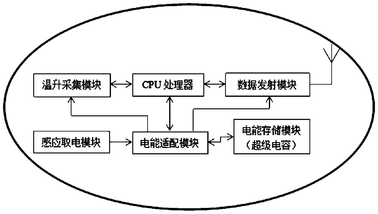
[0007] The purpose of the present invention is to provide a transmission line node temperature rise monitoring device based on inductive power acquisition. By changing the temperature acquisition device and replacing the battery with a super capacitor, the live installation work can be achieved based on the inductive power acquisition technology, which solves the problem of using a battery to supply temperature. The problem of short life of the monitoring device; solves the problem that the monitoring device cannot work normally when the wire current is small by using the induction power technology alone

Method used


Image

  • Temperature rise monitoring device of power transmission line node based on induction electricity taking
  • Temperature rise monitoring device of power transmission line node based on induction electricity taking
  • Temperature rise monitoring device of power transmission line node based on induction electricity taking

Examples


Embodiment Construction

[0035] It should be pointed out that the following detailed description is exemplary and intended to provide further explanation to the present application. Unless defined otherwise, all technical and scientific terms used herein have the same meaning as commonly understood by one of ordinary skill in the art to which this application belongs.

[0036] It should be noted that the terminology used here is only for describing specific implementations, and is not intended to limit the exemplary implementations according to the present application. As used herein, unless the context clearly dictates otherwise, the singular is intended to include the plural, and it should also be understood that when the terms "comprising" and / or "comprising" are used in this specification, they mean There are features, steps, operations, means, components and / or combinations thereof.

[0037] In the present invention, terms such as "upper", "lower", "left", "right", "front", "rear", "vertical", "...


PUM


Abstract

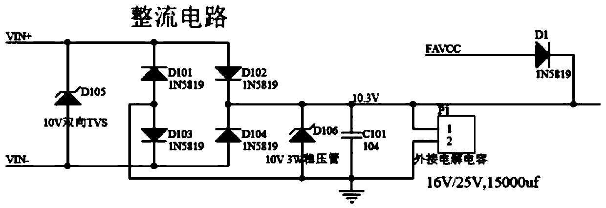
The invention discloses a temperature rise monitoring device of a power transmission line node based on induction electricity taking. The temperature rise monitoring device comprises a signal transceiving unit and an energy supply unit, which are integrated in a closed sealing cover; the energy supply unit comprises an induction electricity taking module, an electric energy adaption module and anenergy storage module; the induction electricity taking module is used for obtaining electric energy from a circuit wire; the electric energy adaption module is connected between the induction electricity taking module and the energy storage module, and an output end of the electric energy adaption module is connected to the signal transceiving unit for performing voltage stabilization on the electric energy obtained by the induction electricity taking module and allocating the electric energy to the signal transceiving unit and the energy storage module; and the energy storage module is a super capacitor. According to thetemperature rise monitoring device disclosed by the invention, by changing a temperature collection device, a battery is replaced by the super capacitor, live installation work is performed based on the induction electricity taking technology, and the problem of short service life of the battery power supply is solved; and the problem that a power supply monitoring device singly using the induction electricity taking technology cannot work normally in the case that the current of the wire is relatively small is solved.

Description

technical field [0001] The invention relates to the technical field of detection equipment, in particular to a device for monitoring temperature rise of transmission line nodes based on inductive power acquisition. Background technique [0002] In recent years, with the continuous growth of the national economy, urban and rural electricity consumption has increased sharply. During the peak period of electricity consumption, the phenomenon that the line power supply load operates near the limit or exceeds the limit occurs from time to time. With the high-load operation of lines becoming more and more common, the excessively high temperature of the connection joints of transmission line wires has become the "death spot" for safe operation of lines. [0003] When the connection point is operated at high temperature, it will be annealed and aged slowly, causing its strength to lose. The strength loss increases with the increase of the clamp temperature and time, and intermittent...

Claims


Application Information

Patent Timeline
Patent Type & Authority Applications(China)
IPC IPC(8): G01K7/18H02J50/10H02J7/00H02J7/34
CPCG01K7/18G01K2215/00H02J7/34H02J50/10
Inventor 李勇辉杨瑞景龙福刚吴卫华王斌曹道林徐惠江黄黔林李定强李华鹏胡洪波吴贵张洪铭胡荣俊吕江江刘宁畅
Owner GUIZHOU POWER GRID CO LTD
Why Eureka
Try Eureka