Tri-tube tri-high-pressure jet grouting pile construction method

A technology of high-pressure rotary grouting piles and construction methods, which is applied in the direction of sheet pile walls, foundation structure engineering, construction, etc., can solve the problems of large soil squeezing effect, small pile diameter, and low work efficiency, so as to reduce the soil squeezing effect, Effect of reducing impact and avoiding damage

Inactive Publication Date: 2019-12-27
北京东地岩土工程有限公司
View PDF10 Cites 8 Cited by
  • Summary
  • Abstract
  • Description
  • Claims
  • Application Information

AI Technical Summary

Problems solved by technology

Conventional high-pressure jet grouting piles have been difficult to meet the needs of ultra-deep underground projects due to a series of defects such as low work efficiency, small pile diameter, and large soil squeezing effect.

Method used


Image

  • Tri-tube tri-high-pressure jet grouting pile construction method
  • Tri-tube tri-high-pressure jet grouting pile construction method

Examples


Embodiment

[0044] An embodiment, a construction method of a triple-tube triple-high-pressure jet grouting pile, is specifically described as follows.

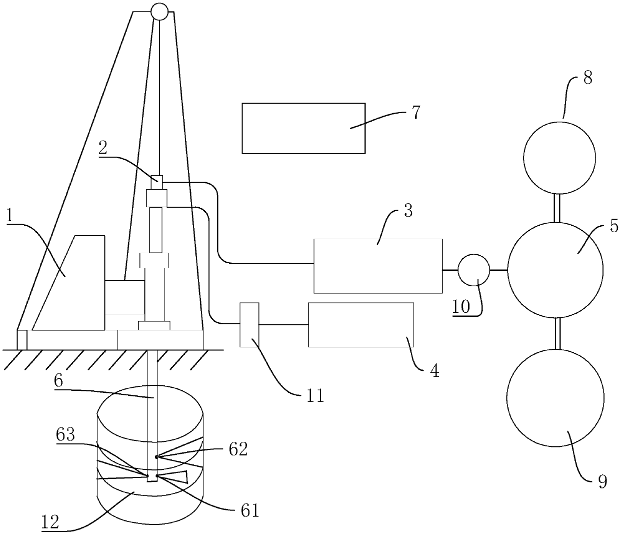
[0045] Such as figure 1 As shown, the main equipment involved in this method includes a model of 300-shaped drilling rig 1, a model of PH-5A triple tube three high-pressure rotary spraying trolley 2, a high-pressure mud pump 3, an air compressor 4, a mortar mixer 5, and a spraying machine. Grouting pipe 6, high-pressure water pump 7, water tank 8, cement silo 9, slurry bucket 10 and gas meter 11. Wherein water tank 8 is connected with cement silo 9 and mortar mixer 5, thereby is used for preparing cement slurry. The mortar prepared in the mortar mixer 5 is sent into the mortar barrel 10 for storage and standby. During rotary grouting, the high-pressure mud pump 3 pumps it into the triple-tube three-high-pressure rotary grouting trolley 2, and injects it into the borehole through the multi-section jet grouting pipe 6 to form a consolidate...


PUM


Abstract

The invention relates to a tri-tube tri-high-pressure jet grouting pile construction method, and belongs to the field of constructional engineering. The tri-tube tri-high-pressure jet grouting pile construction method comprises the following steps: a first step of measuring, paying off and positioning, wherein measurement is performed according to a designed construction drawing, and a construction axis is paid off; a second step of guiding a drilling machine to be in place, wherein the drilling machine is mounted on a designed pile position, and a drill bit of the drilling machine is alignedto the center of the pile position; a third step of drilling, protecting walls and forming holes, wherein the drilling machine is used for drilling holes, and the walls are protected with mud until hole depth achieves designed elevation; a fourth step of separately forming a mud outlet, a water outlet and a gas outlet in the bottom end of a grouting rotary-jetting tube, wherein a pressure value ofair sprayed out by the gas outlet ranges from 1.6 MPa to 2.2 MPa, the water outlet is positioned above the mud outlet and the gas outlet, and the water outlet in the rotary-jetting grouting tube is drilled for washing and reaming while the jetting grouting tube carries out grouting; a fifth step of flushing; and a sixth step of moving the machine. A relatively great gap is formed between the grouting tube and the hole wall, so that pressure in holes is conveniently released, and high water pressure is reduced.

Description

technical field [0001] The invention relates to the field of construction engineering, in particular to a construction method for a triple-tube triple-high-pressure rotary grouting pile. Background technique [0002] The high-pressure rotary grouting pile belongs to the category of high-pressure jet grouting. On the basis of static pressure grouting, it is developed by using high-pressure water jet cutting technology. The double high-pressure rotary grouting method uses the energy of the ultra-high pressure jet fluid movement to destroy the foundation structure, and forms a large-diameter reinforcement by mixing the disturbed soil particles with the hardened material. This technology is widely used, and has the advantages of convenient construction, simple process, quick effect of foundation reinforcement, good durability, short construction period, etc., and has a wide source of materials, low price, low noise, no pollution, no pollution, and no production safety. [0003...

Claims


Application Information

Patent Timeline
Patent Type & Authority Applications(China)
IPC IPC(8): E02D5/46E02D15/04
CPCE02D5/46E02D15/04E02D2250/003
Inventor 赵建军
Owner 北京东地岩土工程有限公司
Why Eureka
Try Eureka