
Self-adaptive second and third harmonic combined detection microimaging method and device

A micro-imaging, self-adaptive technology, applied in applications, diagnostic recording/measurement, medical science, etc., can solve problems such as single-mode aberrations, and achieve the effect of improving imaging depth and imaging quality

Inactive Publication Date: 2019-12-31
HARBIN INST OF TECH
View PDF5 Cites 4 Cited by
  • Summary
  • Abstract
  • Description
  • Claims
  • Application Information

AI Technical Summary

Problems solved by technology

The present invention overcomes the challenges of single detection mode of traditional harmonic microscopic imaging and aberrations in large depth detection

Method used


Image

  • Self-adaptive second and third harmonic combined detection microimaging method and device
  • Self-adaptive second and third harmonic combined detection microimaging method and device

Examples


Embodiment 1

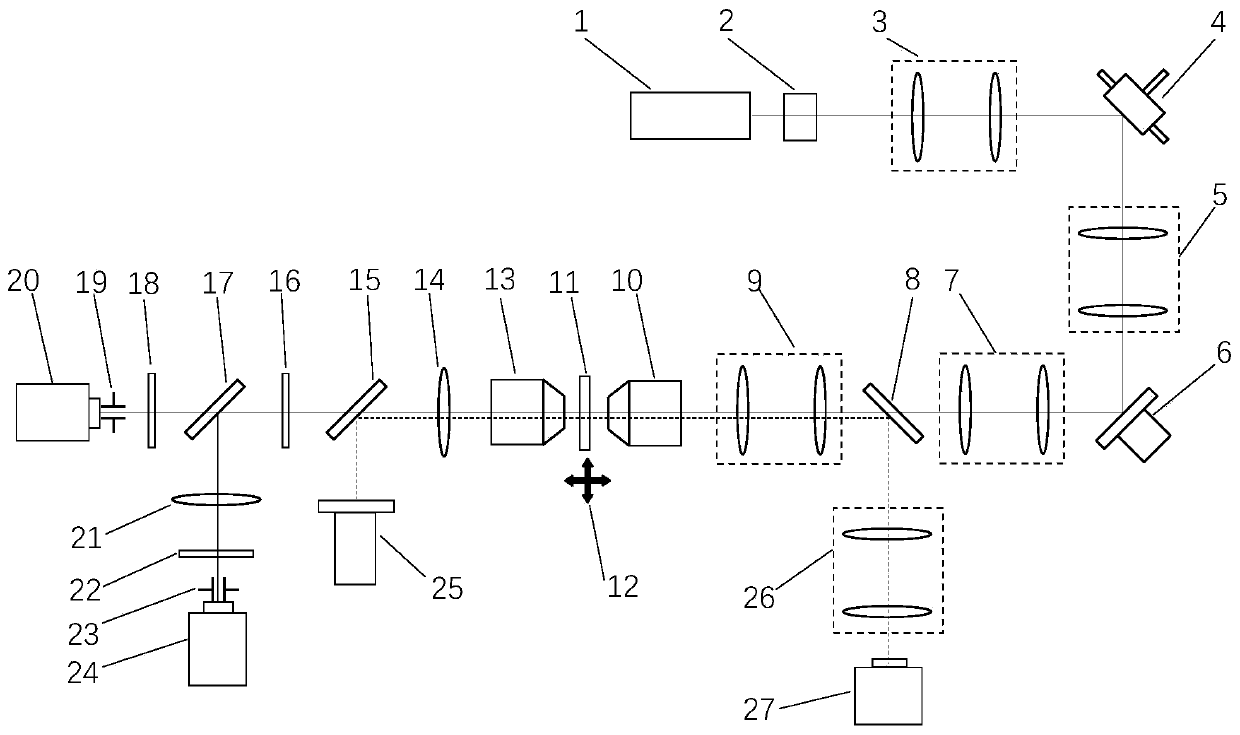
[0041] A schematic diagram of an adaptive second and third harmonic joint detection microscopic imaging device in Embodiment 1 is as follows figure 1shown. The device includes an ultrashort pulse laser light source 1, an optical switch 2, a beam conversion unit 3, a beam scanning element 4, a first lens group 5, a dynamic optical element 6, a second lens group 7, a first dichroic mirror 8, a second lens group Three-lens group 9, microscope objective lens 10, sample 11, three-dimensional micro-displacement stage 12, harmonic signal detection objective lens 13, first lens 14, second dichroic mirror 15, first filter 16, third dichroic Color mirror 17, second harmonic filter 18, first pinhole 19, second harmonic photodetector 20, second lens 21, third harmonic filter 22, second pinhole 23, third harmonic A photodetector 24 , an LED light source 25 , a fourth lens group 26 , and a wide-field imaging camera 27 . The connection relationship of the above-mentioned components is as f...

Embodiment 2

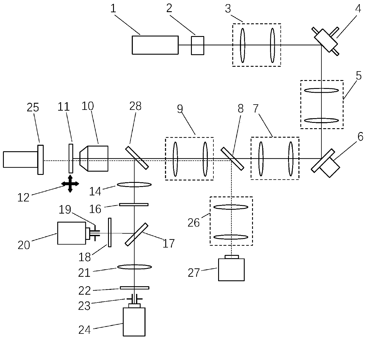
[0047] A schematic diagram of an adaptive second and third harmonic joint detection microscopic imaging device in Embodiment 2 is as follows figure 2 shown. The device includes an ultrashort pulse laser light source 1, an optical switch 2, a beam conversion unit 3, a beam scanning element 4, a first lens group 5, a dynamic optical element 6, a second lens group 7, a first dichroic mirror 8, a second lens group Three-lens group 9, microscope objective lens 10, sample 11, three-dimensional micro-displacement stage 12, first lens 14, first filter 16, third dichroic mirror 17, second harmonic filter 18, first pinhole 19, second harmonic photodetector 20, second lens 21, third harmonic filter 22, second pinhole 23, third harmonic photodetector 24, LED light source 25, fourth lens group 26, Wide-field imaging camera 27 , fourth dichroic mirror 28 . The connection relationship of the above-mentioned components is as follows: the center of the optical surface of all optical compone...


PUM


Abstract

The invention relates to a self-adaptive second and third harmonic combined detection microimaging method and device, and belongs to the technical field of optical microimaging. Second and third harmonic signal detection modules are simultaneously arranged on a detection path of a conventional harmonic microscope device; the separation and wave filtering of second harmonic signals and third harmonic signals are realized by using a dichroscope and a light filter; an independent photoelectric detector is used for respectively detecting the second and third harmonic signals; and a self-adaptive aberration correcting device is introduced into a system, and is used for correcting aberration existing during great-depth detection on a sample. The device provided by the invention comprises a laserscanning system, a self-adaptive aberration correcting system, a harmonic signal exciting system, a harmonic signal detection system, a wide-field imaging system and an image rebuilding and data processing system. The combined detection of the second and third harmonic signals and the complementation of sample structure information are realized; and the imaging quality is maintained during great-depth detection.

Description

technical field [0001] The invention belongs to the field of optical microscopic measurement, and mainly relates to an adaptive second and third harmonic combined detection microscopic imaging method and device for three-dimensional fine structure imaging of living biological samples. Background technique [0002] With the continuous development of science and technology, high-resolution and high-penetration depth imaging of living biological samples has become an indispensable condition for systems biology research. However, due to the existence of the optical diffraction limit, the resolution of traditional optical microscopy imaging is restricted. Fluorescence microscopy enables super-resolution imaging of biological samples. Among them, multiphoton microscopic imaging technology is the best non-invasive fluorescence microscopic imaging method. There is actual energy conversion in the microscopic process of two-photon excitation, and the response time is on the order of...

Claims


Application Information

Patent Timeline
IPC IPC(8): A61B5/00
CPCA61B5/0059A61B5/0033
Inventor 王伟波吴必伟谭久彬
Owner HARBIN INST OF TECH
Learn More