Flue gas condensation heat exchanger with profiling flue gas flow channel structure

A flue gas condensation and flue gas flow technology, which is applied in steam/steam condensers, heat exchanger shells, heat exchange equipment, etc., can solve the problem that the flue gas condensation heat exchanger occupies a large area and the condensation reheating system occupies an area Large space, reducing air humidity and other issues, to achieve the effect of reducing length, avoiding crevice corrosion, and reducing smoke and wind resistance

Pending Publication Date: 2019-12-31
XI AN JIAOTONG UNIV
View PDF0 Cites 1 Cited by
  • Summary
  • Abstract
  • Description
  • Claims
  • Application Information

AI Technical Summary

Problems solved by technology

[0005] In order to realize the deep condensation of water vapor in boiler exhaust smoke, reduce air humidity, and alleviate the problem of smog, the purpose of the present invention is to provide a flue gas condensation heat exchanger with a profiling flue gas flow channel structure, which solves the problem of flue gas The condensing heat exchanger occupies a large area. Through profiling design, the flue gas condensing heat exchanger is connected with the original flue in a compact and low-resistance manner, which solves the problem of large footprint and tight installation space of the condensing reheating system. A major demand for low-cost, low-resistance, high-efficiency and compact flue gas condensation and whitening

Method used


Image

  • Flue gas condensation heat exchanger with profiling flue gas flow channel structure
  • Flue gas condensation heat exchanger with profiling flue gas flow channel structure
  • Flue gas condensation heat exchanger with profiling flue gas flow channel structure

Examples


Embodiment Construction

[0033] The invention will be described in detail below in conjunction with the accompanying drawings and specific embodiments.

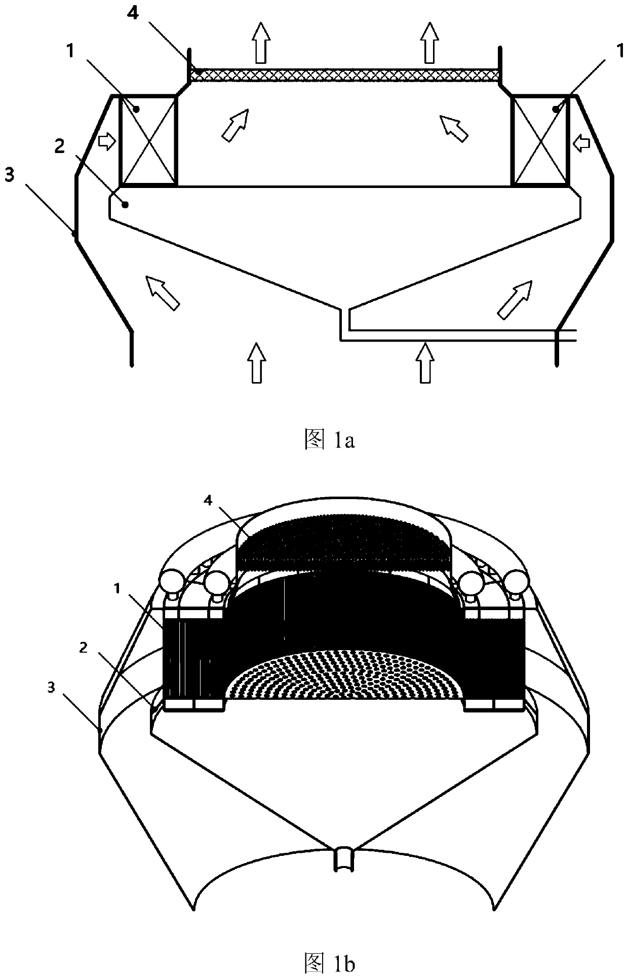
[0034] Such as figure 1 middle figure 1 a and figure 1 As shown in b, a flue gas condensing heat exchanger with a profiling flue gas flow channel structure in the present invention is composed of a flue gas condensing unit 1 , a conical gas distributor 2 , a profiling shell 3 and a demister 4 . The cylindrical part of the profiling shell 3 is connected with the cylindrical flue, the profiling shell 3 has a supporting function, the conical gas distribution plate 2 is fixed in the profiling shell 3; the flue gas condensation unit 1 is placed in the conical gas distribution plate 2; the bottom of the conical gas distribution tray 2 is provided with a condensed water discharge pipe; the demister 4 is provided at the outlet of the profiling shell 3. The flue gas from the original flue is evenly distributed to the inlet surface of the flue gas condensin...


PUM


Abstract

The invention discloses a flue gas condensation heat exchanger with a profiling flue gas flow channel structure. The flue gas condensation heat exchanger is composed of flue gas condensing units, a conical air distribution disc, a profiling outer shell and a demister; a plurality of arc units form the annular flue gas condensing units, flue gas is evenly distributed to the inlet surface of each flue gas condensing unit under the common guidance of the conical air distribution disc and the profiling outer shell, and condensed water is collected in the conical air distribution disc; the flue gascondensing units can use laser welding spiral fin tubes to weaken the crevice corrosion of the condensate water and expand the heat exchange surface, so that the weight of the heat exchanger is remarkably reduced. According to the flue gas condensation heat exchanger, a traditional design is eliminated by traversing a tray of the cross-section of a desulfurization tower, and the flue gas whitening can be achieved by matching an external or built-in flue gas reheater; the shape of the heat exchanger is similar to the shape of an original flue, the flue gas condensation heat exchanger can be installed by replacing part of the original flue, the problem that the occupied space of a condensation reheating system is large and the installation space is stressed is solved, and the important requirements of low cost, low resistance and efficient and compact flue gas condensation and whitening are achieved.

Description

technical field [0001] The invention relates to the field of heat exchangers, in particular to a flue gas condensation heat exchanger with a profiling flue gas flow channel structure. Background technique [0002] In recent years, the smog problem persists, although most coal-fired units have completed ultra-low emission transformation (NOx<50mg / Nm 3 , SO 2 <35mg / Nm 3 , PM10<5mg / Nm 3 ), most of the gas boilers have also completed low-nitrogen modification (NOx<80mg / Nm 3 ). But every year starting from autumn, there are still large areas of smog across the country, although the emission of major air pollutants has dropped significantly compared with the peak in 2013. The generation of smog requires high-humidity environmental conditions. The extensive use of fossil energy will generate a large amount of water vapor, which will significantly increase the air humidity and provide the basic conditions for the growth of smog. Therefore, to further reduce the smo...

Claims


Application Information

Patent Timeline
IPC IPC(8): F23J15/06F23J15/08F28B1/02F28B9/08F28F9/00F28F9/22
CPCF23J15/06F23J15/08F28B1/02F28B9/08F28F9/22F28F9/001F28F2009/222Y02E20/30
Inventor 赵钦新邓世丰严俊杰王云刚梁志远
Owner XI AN JIAOTONG UNIV
Why Eureka
Try Eureka