Efficient external heat type rotary kiln

An external heating, rotary kiln technology, applied in the field of rotary kiln, can solve the problems of equipment material, high strength requirements, unfavorable long-term operation of equipment, inability to effectively heat and other problems, reduce equipment material requirements, and facilitate the utilization of heat. , the effect of reducing thermal stress

Pending Publication Date: 2019-12-31
白太宽
View PDF0 Cites 0 Cited by
  • Summary
  • Abstract
  • Description
  • Claims
  • Application Information

AI Technical Summary

Problems solved by technology

The heat exchange area of ​​jacket heating can only be realized by increasing the equipment area, which has low thermal efficiency and low processing capacity, which affects large-scale production
Radiant tube heating adopts the air intake method of the external hot flue gas chamber. The external hot flue gas chamber is set near the middle of the rotary kiln. The materials at the hot flue gas inlet and the discharge end cannot be heated effectively, and the heat utilization rate is low.
The temperature of the hot flue gas in contact with the equipment is very high, the material and strength of the equipment are high, the thermal stress is difficult to eliminate, and the heat loss increases, which not only increases the equipment investment, but also is not conducive to the long-term operation of the equipment

Method used


Image

  • Efficient external heat type rotary kiln
  • Efficient external heat type rotary kiln
  • Efficient external heat type rotary kiln

Examples


Embodiment 1

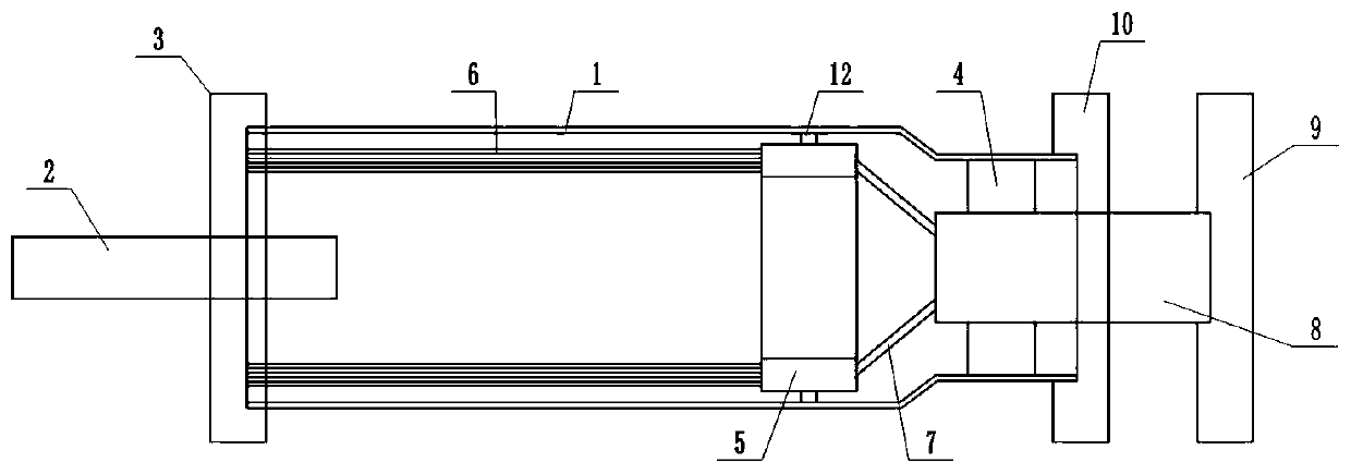
[0019] Such as figure 1 As shown, the high-efficiency externally heated rotary kiln includes a kiln body 1. The feed end of the kiln body 1 is equipped with a screw conveyor 2 and a low-temperature flue gas collection chamber 3, and the screw conveyor 2 penetrates through the low-temperature flue gas collection chamber 3 and discharges The mouth extends into the kiln body and is arranged on the central axis of the kiln body 1. A pyrolysis material collection device is installed at the discharge end of the kiln body 1, and an annular high-temperature flue gas distribution chamber 5 is installed on the inner wall of the kiln body 1 near the discharge end. One side of the annular high-temperature flue gas distribution chamber 5 is communicated with the low-temperature flue gas collection chamber 3 through a plurality of flue gas heat exchange tubes 6, and the inner wall of the kiln body 1 is provided with a plurality of supporting mechanisms for supporting the flue gas heat exchange...

Embodiment 2

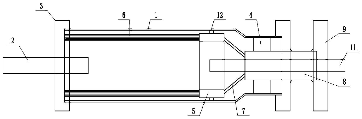
[0024] Such as figure 2 As shown, the pyrolysis material collection device is mainly composed of a pyrolysis material collection cover 10 and a pyrolysis gas conveying pipe 11. The pyrolysis material collection cover 10 is rotated and sealed with the discharge end of the kiln body 1, and the bottom of the pyrolysis material collection cover 10 The pyrolysis material discharge port is provided, the pyrolysis gas conveying pipe 11 penetrates the high temperature flue gas collecting chamber 9, the pyrolysis material collecting cover 10 extends to the inside of the kiln body 1, and the pyrolysis gas conveying pipe 11 and the high temperature flue gas central pipe 8 is arranged concentrically, the pyrolysis gas conveying pipe 11 and the high-temperature flue gas collecting chamber 9 and the pyrolysis material collecting cover 10 are rotated and sealed, and the outer wall of the pyrolysis gas conveying pipe 11 is provided with a thermal insulation layer. The rest is the same as the f...

Embodiment 3

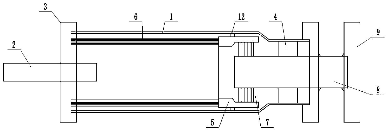
[0027] Such as image 3 As shown, when the high-temperature flue gas central pipe 8 extends to the center of the annular high-temperature flue gas distribution chamber, one end of the annular high-temperature flue gas distribution chamber is provided with a taper. The rest is the same as the first embodiment. The high-temperature flue gas central pipe extends to the center of the annular high-temperature flue gas distribution chamber. In order to ensure that the high-temperature flue gas distribution chamber and the high-temperature flue gas central pipe have sufficient discharge space, one end of the high-temperature flue gas distribution chamber is provided with a taper to ensure the discharge volume.

[0028] Example three

[0029] Such as Figure 4 As shown, when the high-temperature flue gas central pipe 8 extends to the center of the annular high-temperature flue gas distribution chamber, one end of the annular high-temperature flue gas distribution chamber is provided with ...


PUM


Abstract

The invention relates to an efficient external heat type rotary kiln, and belongs to the technical field of rotary kilns. The efficient external heat type rotary kiln specifically comprises a spiral conveyor and a low-temperature flue gas collection chamber, the spiral conveyor and the low-temperature flue gas collection chamber are arranged at the feeding end of a kiln body, the spiral conveyor penetrates through the low-temperature flue gas collection chamber, the discharging end of the kiln body is provided with a pyrolysis material collecting device, an annular high-temperature flue gas distribution chamber is arranged on the inner wall, close to the discharge end, of the kiln body, one side of the annular high-temperature flue gas distribution chamber is in communication with the low-temperature flue gas collection chamber through a plurality of flue gas heat exchange tubes, the other side of the annular high-temperature flue gas distribution chamber is in communication with a high-temperature flue gas central tube through a high-temperature flue gas conduit, the end of the high-temperature flue gas center tube is provided with a high-temperature flue gas collection chamber, and the high-temperature flue gas collection chamber is connected with a high-temperature flue gas tube. According to the efficient external heat type rotary kiln, the design is reasonable, the flue gas chamber is not in direct contact with the kiln body, the kiln body deformation caused by too high temperature of the kiln body can be effectively avoided, and the heat loss is small.

Description

Technical field [0001] The invention relates to a high-efficiency external heating type rotary kiln, belonging to the technical field of rotary kilns. Background technique [0002] In the well-known rotary kiln heating device, there are two internal heating methods and external heating methods. The internal heating directly contacts the heating medium with the heated medium, so that the produced volatile gas has a low calorific value and can be used later. Low, not only causes energy waste, but also runs counter to the clean and efficient use policy. The external heating method currently announced includes jacket heating and radiant tube heating. The heat exchange area of ​​jacketed heating can only be achieved by increasing the area of ​​the equipment, with low thermal efficiency and low processing capacity, which affects large-scale production. The radiant tube heating adopts the air intake method of the external hot flue gas chamber. The external hot flue gas chamber is set ...

Claims


Application Information

Patent Timeline
Patent Type & Authority Applications(China)
IPC IPC(8): F27B7/08F27B7/34F27B7/42
CPCF27B7/08F27B7/34F27B7/42
Inventor 张丰阁施俊鹏
Owner 白太宽
Why Eureka
Try Eureka