
Exhaust cylinder and method for wet dust removal and purification

A technology of wet dust removal and exhaust stack, which is applied in the direction of chemical instruments and methods, separation methods, and separation of dispersed particles, which can solve the problems of reducing the moisture content of flue gas, occupying a large area of ​​equipment, and large investment at one time, so as to reduce The effect of occupying an area, improving dehydration efficiency, and good sealing effect

Active Publication Date: 2021-11-05
BERIS ENG & RES CORP
View PDF7 Cites 0 Cited by
  • Summary
  • Abstract
  • Description
  • Claims
  • Application Information

AI Technical Summary

Problems solved by technology

[0004] Aiming at the existing technical problems that the dehydration, whitening and discharge of wet flue gas are independently set up with functional sections, the whole process system has a large investment at one time, the equipment occupies a large area, and the system resistance is large. The present invention aims to provide a method for The exhaust pipe and method of wet dust removal and purification can realize the efficient removal of mechanical water carried by wet flue gas in various wet dust removal and purification systems, reduce the moisture content in the flue gas, and at the same time heat the flue gas Heating, keeping the flue gas away from the saturated state, and achieving the purpose of whitening emission reduction, and the device has small resistance, and the equipment occupies a small area, and can realize dehydration and whitening emission at the same time

Method used


Image

  • Exhaust cylinder and method for wet dust removal and purification
  • Exhaust cylinder and method for wet dust removal and purification

Examples


Embodiment 1

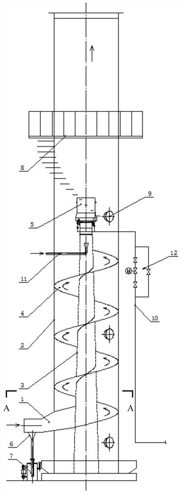
[0028] First of all, it should be noted that the specific implementation of this embodiment relies on the gas supply system 10 and the combustion-supporting gas supply system 11 that can be independently controlled.

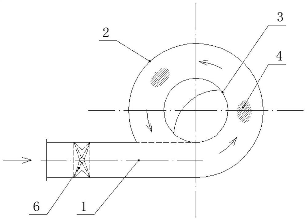
[0029] This embodiment discloses an exhaust cylinder for wet dust removal and purification, which includes a cylinder body 2, a core tube 3, a spiral partition 4, a heating mechanism and a water collecting funnel 6, and the core tube 3 is installed inside the cylinder body 2. A heating mechanism is installed on the top of the core tube 3, and the heating mechanism is used to heat the dehydrated flue gas. A water collecting funnel 6 is installed at the bottom of the exhaust tube body. There is a gap between the core tube 3 and the exhaust tube body. The spiral partition 4 is installed Between the cylinder body 2 and the core tube 3, a continuous spiral channel is formed, and the spiral channel is used to provide a centrifugal force channel to realize the gas-water ...


PUM


Abstract

The invention discloses an exhaust cylinder and method for wet dust removal and purification, comprising a cylinder body, a core tube, a spiral partition, a heating mechanism and a water collecting funnel, the core tube is installed inside the cylinder body, and the top of the core tube is installed for heating Mechanism, the heating mechanism is used to heat the dehydrated flue gas, the water collecting funnel is installed at the bottom of the exhaust cylinder, there is a gap between the core tube and the exhaust cylinder, and the spiral partition is installed between the cylinder and the core tube, A continuous spiral channel is formed, and the spiral channel is used for heating and discharging the dehydrated flue gas.

Description

technical field [0001] The invention relates to the field of environmental protection machinery, in particular to an exhaust cylinder for wet dust removal and purification. Background technique [0002] In the wet desulfurization system and other wet dust removal and purification systems, a large amount of water needs to be sprayed into the system for cooling and dust removal and purification. During this process, the flue gas often contains a large amount of water droplets, which will produce A large number of white smoke plumes also cause a lot of waste of water resources. At present, with the continuous improvement of national environmental protection standards, the control of smoke plume at the exhaust pipe has gradually become an assessment item for the environmental protection department's environmental protection requirements for polluting enterprises. [0003] At present, independent functional sections are generally set up for the dehydration, whitening, and discha...

Claims


Application Information

Patent Timeline
Patent Type & Authority Patents(China)
IPC IPC(8): B01D45/02B01D45/16B01D53/00
CPCB01D45/02B01D45/16B01D53/00
Inventor 郑运兴吕炎姜洋王志远
Owner BERIS ENG & RES CORP
Learn More