

Method for machining turbine rotor with special-shaped center hole
A processing method and technology of turbine rotors, which are applied to the supporting elements of blades, engine elements, machines/engines, etc., can solve problems such as different forces on the center holes at both ends, production limitations, and floating value of the outer circle of the turbine shaft. Improve the dimensional and geometric tolerances of each file, and the effect of strong reliability
- Summary
- Abstract
- Description
- Claims
- Application Information
AI Technical Summary
Problems solved by technology
Method used
Image

Examples
Embodiment Construction
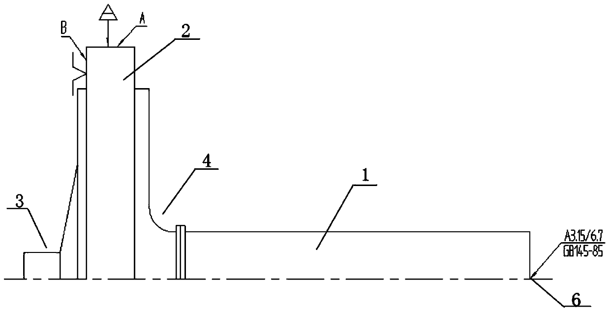
[0082] Such as Figure 1 to Figure 14 Shown, a kind of processing method of turbine rotor with special-shaped center hole, this method comprises the following steps:
[0083] Step 10 Solder One
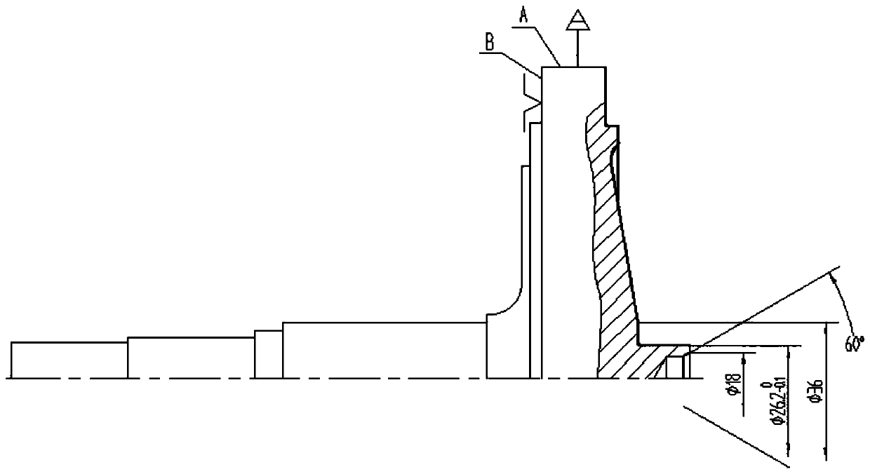
[0084] Take the turbine disk 2 and the optical axis of the turbine shaft 1, and after cleaning, weld the compressor end 4 of the turbine disk to the optical axis of the turbine shaft 1, and the center hole of the turbine end 3 of the turbine disk is provided with a special-shaped center hole 7;
[0085] Specific processing method: Clean the turbine disk and turbine optical shaft with acetone. 29.8 outer circle).
[0086] Step 20 carries out the first heat treatment to the workpiece after welding;
[0087] Carry out heat treatment according to the company's technical standards, and inspect the mechanical properties.
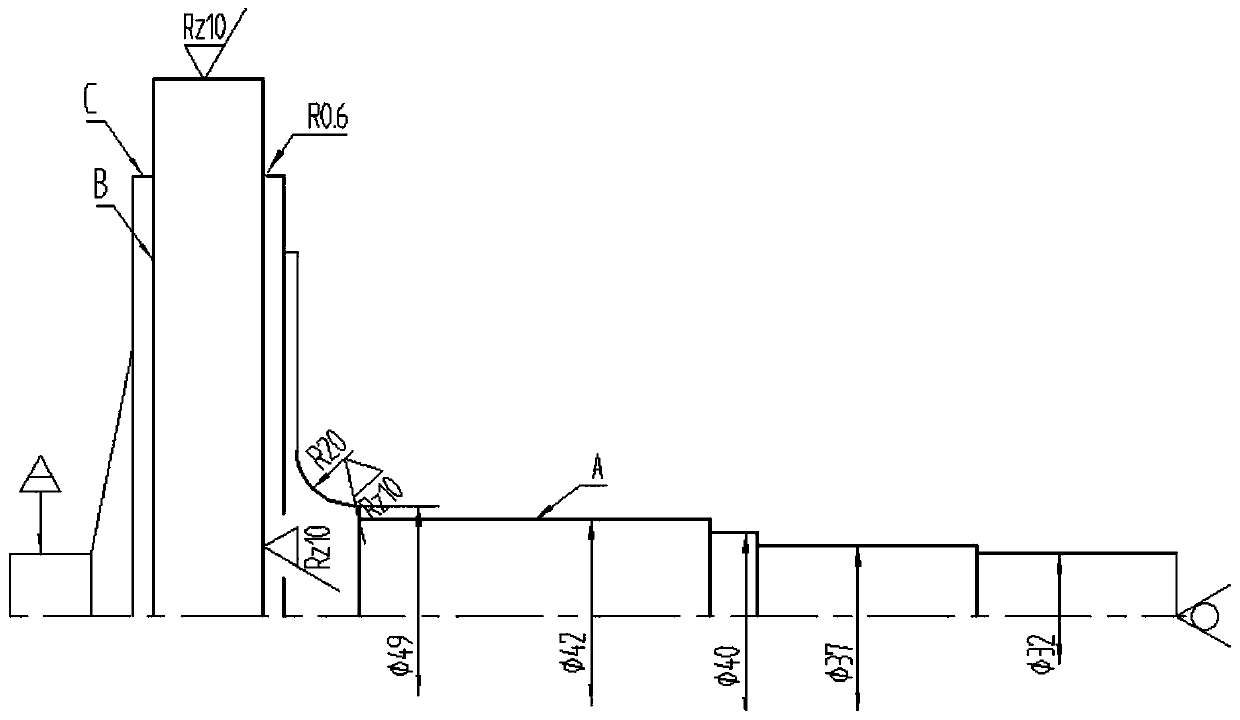
[0088] Step 30 Rough car
[0089] Drill the center hole, remove the outer circle and end face allowance of the turbine disc, and remove the outer circle and end fac...
PUM
 Abstract
Description
Claims
Application Information