Automatic welding device and method for marine low-speed diesel engine branch pipe flange

A branch pipe flange and automatic welding technology, which is applied in welding equipment, auxiliary equipment, welding equipment, etc., can solve the problems of poor working conditions of welding operators, damage to human eyes and skin, unstable welding quality, etc., and achieve improved operation Conditions and labor intensity, eliminate welding spatter, and the effect of stable weld quality

Inactive Publication Date: 2020-01-07
CSSC MES DIESEL
View PDF7 Cites 7 Cited by
  • Summary
  • Abstract
  • Description
  • Claims
  • Application Information

AI Technical Summary

Problems solved by technology

In the welding process of branch pipe flanges, welding operators are required to have high professional skills, and must be able to operate both argon arc welding and gas shielded welding; on the other hand, during the welding process of pipes, ultraviolet rays (UVR ) and infrared rays (IFR) can cause serious damage to human eyes and skin. In addition, during welding, the welding core, coating and metal base material in the electrode will undergo melting, evaporation, oxidation, and agglutination under the high temperature of the arc. A large amount of smoke and dust of metal oxides and other substances are produced, and long-term inhalation may cause pneumoconiosis of operators; moreover, welding operators may also cause unstable welding quality due to their poor working conditions

Method used


Image

  • Automatic welding device and method for marine low-speed diesel engine branch pipe flange
  • Automatic welding device and method for marine low-speed diesel engine branch pipe flange
  • Automatic welding device and method for marine low-speed diesel engine branch pipe flange

Examples


Embodiment Construction

[0041] The present invention will be described in detail below in conjunction with the accompanying drawings and embodiments. All equivalent changes and modifications made according to the contents of this specification shall fall within the scope of protection claimed by the application of the present invention.

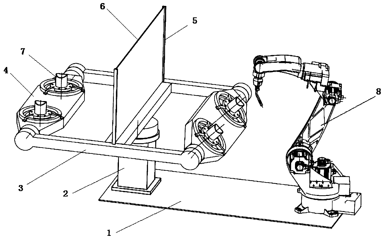
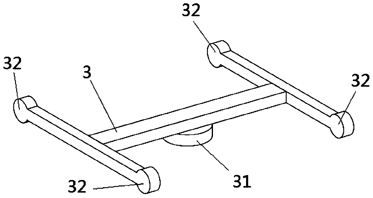
[0042] see figure 1 , figure 1 It is an automatic welding device for branch pipe flanges of marine low-speed diesel engines, which can be used for pipe diameters of Automatic welding of branch pipes and flanges. The automatic welding device includes a bottom plate 1 , a base 2 , an H-shaped horizontal beam 3 , two overturning bodies 4 , two baffle brackets 5 , an arc-proof baffle 6 and a welding robot 8 .

[0043] The bottom plate 1 is located at the lowermost part and is the basis of the whole device.

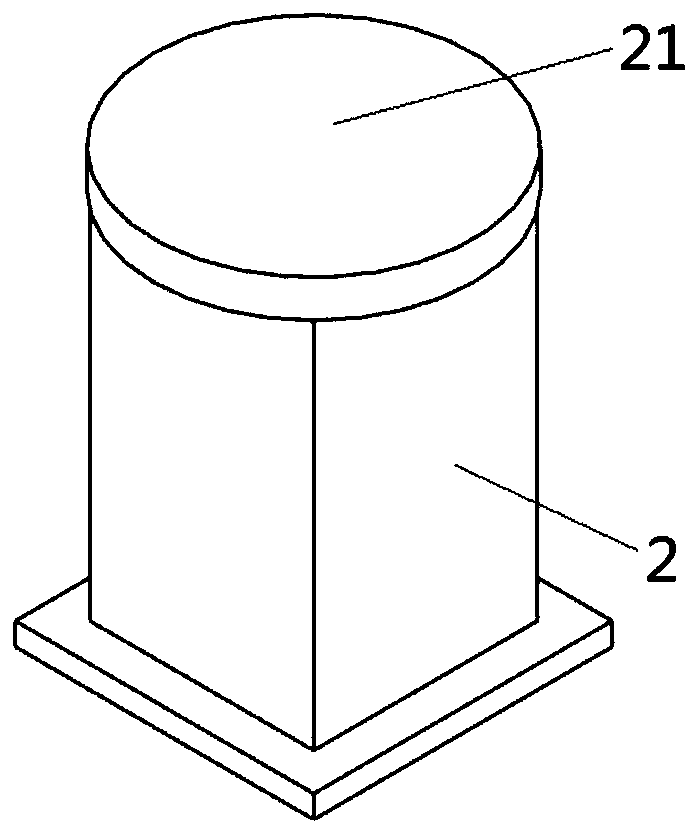
[0044] The base 2 and the welding robot 8 are respectively fixedly installed on both sides above the base plate 1 .

[0045] see figure 2 , the lower part o...


PUM


Abstract

The invention discloses an automatic welding device and method for a marine low-speed diesel engine branch pipe flange. The automatic welding device comprises a bottom plate, a base, an I-shaped horizontal beam, two turning bodies, two baffle supports, an anti-arc baffle and a welding robot, wherein the base and the welding robot are installed on the upper side of the bottom plate, the center of the I-shaped horizontal beam is connected with the base through a servo motor horizontal rotating mechanism and horizontally rotates, the ends of the four corners of the I-shaped horizontal beam are fixedly provided with servo motor perpendicular rotating mechanisms, the two ends of each turning body are connected with the servo motor perpendicular rotating mechanisms at the ends of the two cornersof the same side of the I-shaped horizontal beam correspondingly and driven by the servo motor perpendicular rotating mechanisms to perpendicularly rotate, each turning body is provided with a hollowclamp, the anti-arc baffle is perpendicularly fixed to the middle of the I-shaped horizontal beam through the baffle supports, the welding robot is fixed to the bottom plate on one side of the I-shaped horizontal beam, and the I-shaped horizontal beam rotates between personnel and the welding robot so that manual operation and the automatic welding station can be switched. By means of the automatic welding device and method, operation conditions are improved, labor intensity is reduced, and the welding quality is improved.

Description

technical field [0001] The invention relates to the manufacture of marine low-speed diesel engines, in particular to an automatic welding device and method for branch pipe flanges of marine low-speed diesel engines, and belongs to the technical field of diesel engine manufacturing. Background technique [0002] In the production of marine low-speed diesel engine pipe fittings, the pipes of each pipe system need to be pair-welded. According to the order of grouping, the branch pipe and the flange are first pair-welded. After the branch pipe flange is welded, as a whole The components are then paired with other runs. The particularity of the butt welding between the branch pipe flange and other pipe groups is that the structural form of the branch pipe flange is relatively simple, and the structures of workpieces of various specifications are similar, and there is no complicated direction similar to other pipelines, so batch production can be carried out. production. [0003...

Claims


Application Information

Patent Timeline
Patent Type & Authority Applications(China)
IPC IPC(8): B23K9/00B23K9/32B23K37/047
CPCB23K9/00B23K9/32B23K37/047
Inventor 张义王苏南周文新张勤
Owner CSSC MES DIESEL
Why Eureka
Try Eureka