Stacking machine lifting and travelling chain transmission structure and stacking machine

A chain transmission mechanism and chain transmission technology are applied in the direction of conveyor objects, stacking of objects, and de-stacking of objects, which can solve problems such as large power requirements, complex equipment, and heavy weight, saving labor and reducing labor costs. , the effect of simple structure

Pending Publication Date: 2020-01-07
天津市隆达工业自动化设备有限公司
View PDF2 Cites 2 Cited by
  • Summary
  • Abstract
  • Description
  • Claims
  • Application Information

AI Technical Summary

Problems solved by technology

Using the conveyor belt, brick pushing mechanism, stepping line body and palletizing mechanism, according to the required stacking combination, the bricks are arranged in advance through the conveyor belt and stepping line body to form a combination, and the stacking mechanism directly The combination is moved or rotated for stacking; due to the heavy weight of the brick layer, the power required to drive the mechanical arm to drive the brick layer up and down is relatively large, and the equipment is relatively more complicated

Method used


Image

  • Stacking machine lifting and travelling chain transmission structure and stacking machine
  • Stacking machine lifting and travelling chain transmission structure and stacking machine
  • Stacking machine lifting and travelling chain transmission structure and stacking machine

Examples


Embodiment 1

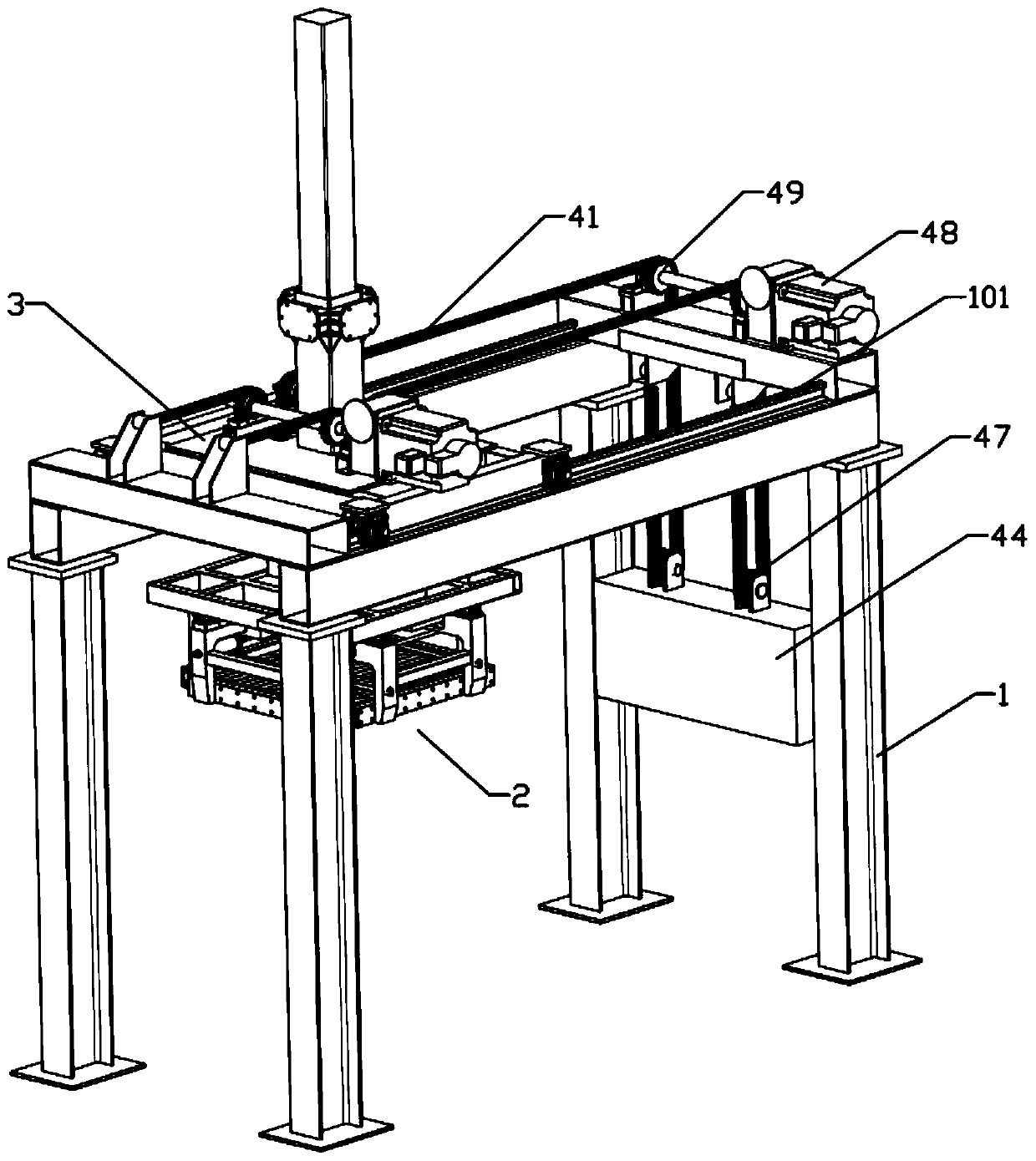
[0039] Example 1: Please also see Figure 1 to Figure 7 , A preferred embodiment of the present invention provides a palletizer lifting and walking chain transmission structure and a palletizer comprising the palletizing machine lifting and walking chain transmission structure;

[0040] Specifically, the lifting and walking chain transmission structure of the palletizer includes a frame 1 and a stacking fixture 2, the frame 1 is provided with a running trolley 3, and the running trolley 3 is slidably provided with the stacking fixture 2 ; It also includes a chain transmission mechanism 4, which is used to drive the running trolley 3 to move on the frame 1, and to drive the palletizing fixture 2 to move up and down.

[0041] Specifically, the chain transmission mechanism 4 includes a chain 41 fixed at both ends relative to the frame 1, and a steering part 42 that is arranged on the palletizing fixture 2 and cooperates with the chain 41, which is driven relative to the The runn...

Embodiment 2

[0043] Example 2: Please also see Figure 1 to Figure 7 , a preferred embodiment of the present invention provides a palletizer lifting and walking chain transmission structure and a palletizer comprising the palletizing machine lifting and walking chain transmission structure, the difference from Embodiment 1 is only:

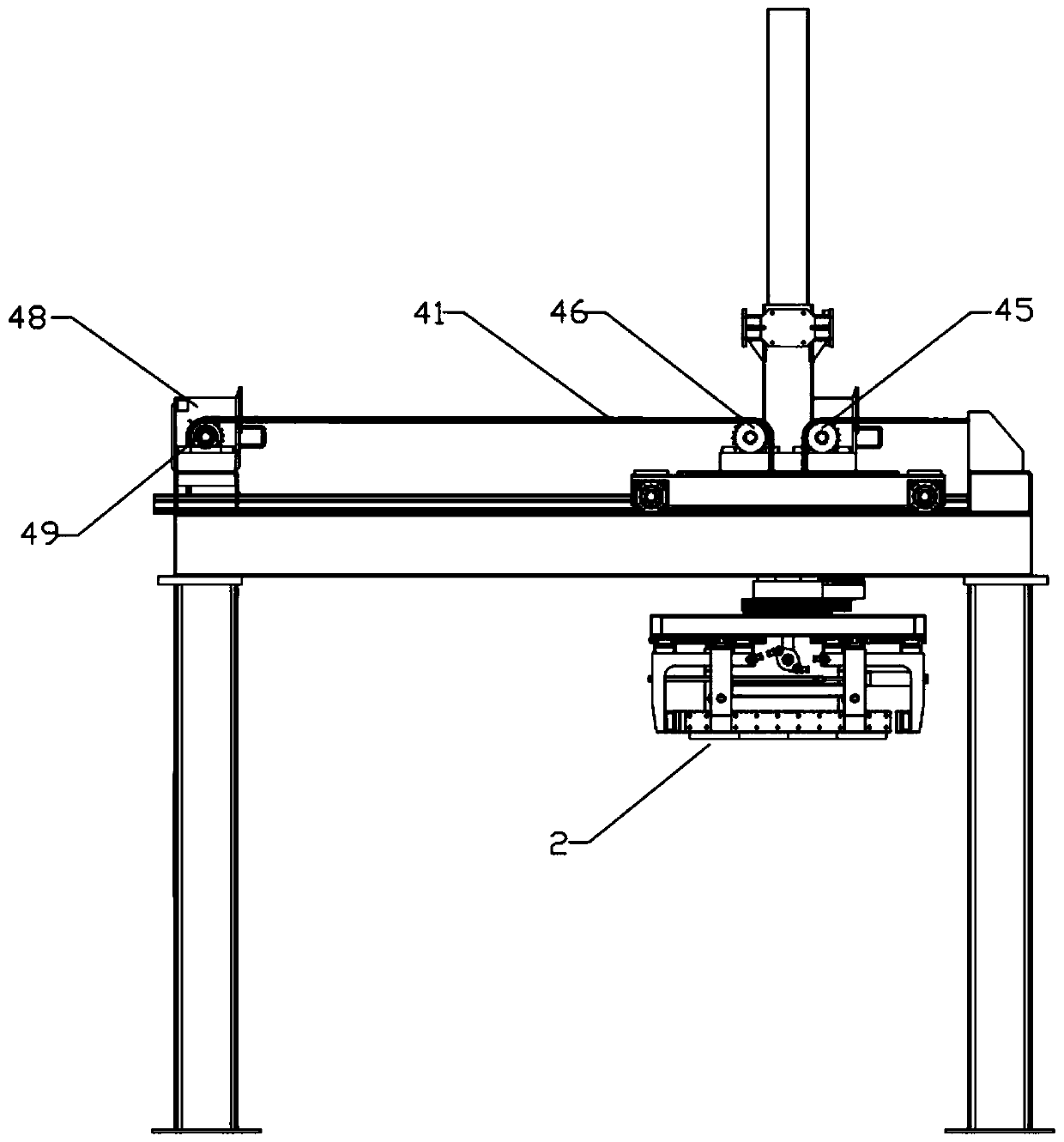
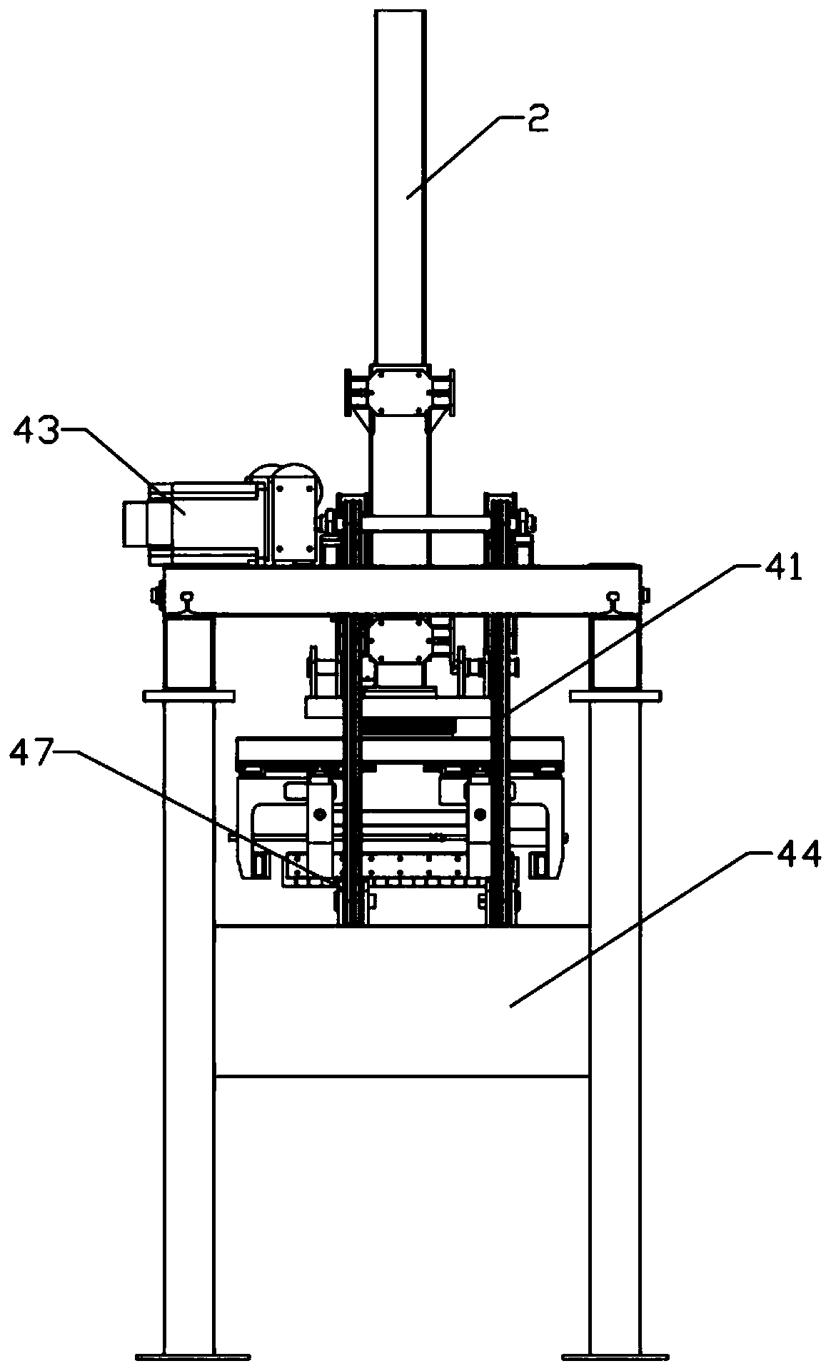
[0044]The chain transmission mechanism 4 also includes a driving gear 45 connected to the output end of the first motor 43 and a driven gear 46 provided on the running trolley 3 , both of which are engaged with the chain 41 .

[0045] In this embodiment, the steering part 42 is set as a gear meshed with the chain 41, and the steering part 42 and the driving gear 45 and the driven gear 46 are distributed in the shape of "pin"; the chain 41 It meshes with the driving gear 45, the steering part 42, and the driven gear 46 in turn.

[0046] In this embodiment, the bearing block 44 is connected with a movable pulley 47 , and the movable pulley 47 is engaged and sus...

Embodiment 3

[0052] Example 3: Please also see Figure 1 to Figure 10 , a preferred embodiment of the present invention provides a palletizer that includes the palletizer lifting and walking chain transmission structure, and its difference from Example 2 is only:

[0053] It also includes an integration mechanism 5, the integration mechanism 5 includes a first transmission mechanism 51, a second transmission mechanism 52 and the rake claw 53 that can move horizontally, the first transmission mechanism 51 and the second transmission mechanism 52 Arranged in parallel, the rake claws 53 are installed at the connection between the first transmission mechanism 51 and the second transmission mechanism 52 through the support frame 54, and are used to transfer the brick row on the first transmission mechanism 51 to the second transmission mechanism in batches one by one. Two transmission mechanisms 52 .

[0054] In this embodiment, a third motor 55 is installed on the support frame 54, the output...


PUM


Abstract

The invention relates to the technical field of stacking equipment, and discloses a stacking machine lifting and travelling chain transmission structure. The stacking machine lifting and travelling chain transmission structure comprises a machine frame and a stacking clamp, wherein a running trolley is arranged on the machine frame, and the stacking clamp is slidably arranged on the running trolley; and the structure further comprises a chain transmission mechanism, the chain transmission mechanism comprises a chain, a steering part, a first motor and a bearing block, wherein the two ends of the chain are fixed relative to the machine frame, the steering part is arranged on the stacking clamp and cooperates with the chain, the steering part is ascended and descended relative to the runningtrolley under driving, the first motor is in transmission connection with the chain to realize horizontal movement of the running trolley, and the bearing block is in transmission connection with thechain so as to realize ascending and descending of the stacking clamp. According to the stacking machine lifting and travelling chain transmission structure, automatic stacking of brick layers can beachieved, the structure is simple, and the brick layers can be driven to ascend and descend and move without large power output. The invention further provides a stacking machine.

Description

technical field [0001] The invention relates to the technical field of palletizing equipment, in particular to a palletizing machine lifting and walking chain transmission structure and a palletizing machine. Background technique [0002] At present, there are nearly 200,000 brick factories in my country, covering an area of ​​nearly 10,000 hectares, and with the development of society, there is an increasing trend. After the brick kiln produces bricks, it is necessary to palletize the bricks. The traditional palletizing method is manual operation, which has high labor intensity, low efficiency and high cost. Therefore, it is urgent to design palletizing equipment to replace manual palletizing. [0003] Existing stacking equipment is mainly push-type and mechanical arm type. Push-type stacking equipment, such as the Chinese invention patent with the authorized announcement number CN103552832B, discloses a brick unloading stacking unit and a brick unloading stacking method fo...

Claims


Application Information

Patent Timeline
Patent Type & Authority Applications(China)
IPC IPC(8): B65G61/00B65G57/22B65G47/82
CPCB65G47/82B65G57/22B65G61/00
Inventor 刘建民刘雅萱
Owner 天津市隆达工业自动化设备有限公司
Why Eureka
Try Eureka