Combustion type optical fiber preform stretching apparatus and control method thereof

A technology of optical fiber preform and stretching equipment, applied in glass manufacturing equipment, manufacturing tools, etc., can solve the problems of complex structure, large volume of high-frequency induction furnace, etc., achieve the effect of small size, improve work efficiency, and realize integrated control

Inactive Publication Date: 2020-01-10
FENGHUO COMM SCI & TECH CO LTD +1
View PDF5 Cites 1 Cited by
  • Summary
  • Abstract
  • Description
  • Claims
  • Application Information

AI Technical Summary

Problems solved by technology

[0005] The object of the present invention is to provide a combustion type optical fiber preform drawing equipment and its control method in order to overcome the disadvantages of large volume and complicated structure of the high-frequency induction furnace of the induction drawing equipment in the above-mentioned background technology

Method used


Image

  • Combustion type optical fiber preform stretching apparatus and control method thereof
  • Combustion type optical fiber preform stretching apparatus and control method thereof
  • Combustion type optical fiber preform stretching apparatus and control method thereof

Examples


Embodiment 1

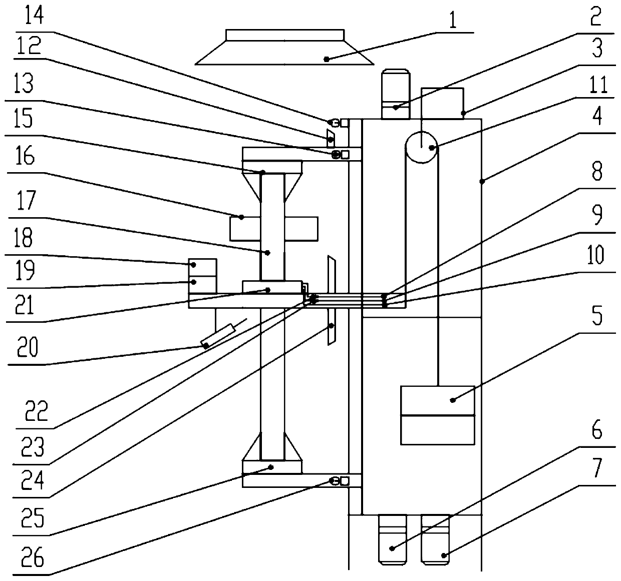
[0032] see figure 1 As shown, the embodiment of the present invention provides a combustion type optical fiber preform drawing equipment, including:

[0033]The main body of the tower, the main body of the tower includes: a tower 4 , an upper chuck device 15 , a lower chuck device 25 and an annular blowtorch 21 . The upper chuck device 15 is installed on the upper end of a pair of vertical guide rails on the front of the tower 4 through the upper chuck lifting device. The upper chuck device 15 is used to clamp the optical fiber preform 17 to move upward. The disc carrier is fixedly installed at the lower end of a pair of vertical guide rails on the front of the tower frame 4. The upper chuck device 15 and the lower chuck device 25 are used to clamp the two ends of the optical fiber preform 17 and drive the optical fiber preform 17 to rotate . The upper chuck device 15 moves up and down freely following the upper chuck lifting device to stretch the optical fiber preform 17 to...

Embodiment 2

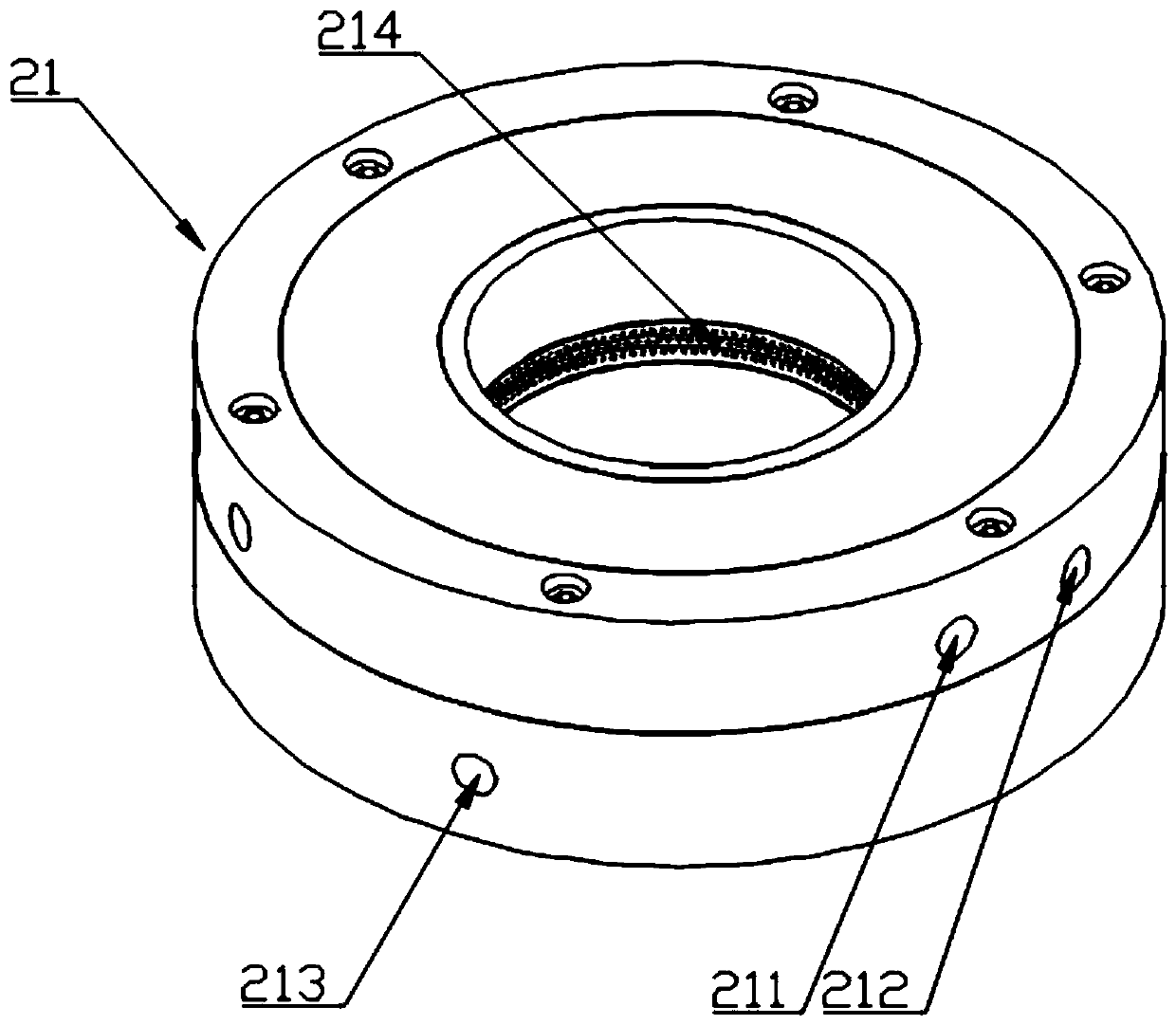
[0040] see figure 2 and image 3 As shown, the embodiment of the present invention provides a combustion-type optical fiber preform drawing equipment. Compared with Embodiment 1, the difference between this embodiment is that the annular blowtorch 21 is a circular structure and a hollow body, and the annular blowtorch 21 adopts Ablation-resistant metallic or ceramic materials. A hydrogen gas inlet 211 and an oxygen gas inlet 212 are provided on the outer wall of the annular blowtorch 21, and the diameters of the hydrogen gas inlet 211 and the oxygen gas inlet 212 are about 10 mm. A plurality of flame holes 214 are arranged on the inner wall of the annular torch 21, and the diameter of the flame holes 214 is about 0.6mm. A plurality of flame holes 214 are uniformly arranged in a ring along the inner wall of the annular torch 21 , and the specific number, arrangement and shape of the flame holes 214 can be specifically set according to actual needs.

[0041] A closed gas mix...

Embodiment 3

[0044] see figure 2 and image 3 As shown, the embodiment of the present invention provides a combustion-type optical fiber preform drawing equipment. Compared with Embodiment 2, the difference between this embodiment is that a process cooling water system is also provided in the ignition cabinet, and the process cooling water system The cooling water pipeline 10 is provided with a filter and a hand valve, the hand valve is used to control the flow of the cooling water pipeline 10 of the process cooling water system, and the filter is used to filter impurities in the cooling water. A water inlet 213 and a water outlet are also provided on the outer wall of the annular torch 21, and the water inlet 213 and the water outlet are far away from each other. A liquid cooling chamber 216 is provided between the outer wall and the inner wall of the annular blowtorch 21. The liquid cooling chamber 216 is an annular structure. The water pipeline 10 communicates, and the water outlet c...


PUM


Abstract

The invention discloses a combustion type optical fiber preform stretching apparatus and a control method thereof, and belongs to the technical field of optical fiber preform production apparatuses. The apparatus comprises: a tower main body, wherein the tower main body comprises a tower, an upper chuck device, a lower chuck device and an annular blowtorch, the annular blowtorch is mounted in themiddle position of a pair of vertical guide rails on the front surface of the tower through a blowtorch lifting device, and an igniter is arranged beside the annular blowtorch; an ignition cabinet, wherein a hydrogen supply pipeline and an oxygen supply pipeline which are connected with the annular blowtorch are arranged in the ignition cabinet, the hydrogen supply pipeline is provided with a hydrogen flow meter and a hydrogen valve assembly, and the oxygen supply pipeline is provided with an oxygen flow meter and an oxygen valve assembly; and a control cabinet, wherein a PLC and a control panel are arranged in the control cabinet, and the control panel is in communication connection with the PLC. The apparatus has the advantages of high automation degree, good stability, suitableness forlarge-scale production, and facilitation of later apparatus maintenance and product upgrading due to large stock and convenient purchasing of the PLC on the market.

Description

technical field [0001] The invention relates to the technical field of optical fiber preform production equipment, in particular to a combustion type optical fiber preform drawing equipment and a control method thereof. Background technique [0002] With the development of 5G communication technology, optical fiber manufacturing technology is also constantly improving to meet the increasing demand for transmission capacity. Compared with some classic transmission methods such as wireless transmission communication and electrical transmission communication, optical transmission communication has a large capacity. High-speed, long-distance communication transmission has a good advantage, and the application prospect is very broad. Therefore, higher requirements are placed on equipment performance and processing accuracy in the processing or handling of optical fiber preforms. [0003] Induction stretching equipment uses a high-frequency induction furnace as the heating part, ...

Claims


Application Information

Patent Timeline
Patent Type & Authority Applications(China)
IPC IPC(8): C03B37/012
CPCC03B37/01242
Inventor 叶子文程康喻煌郭君
Owner FENGHUO COMM SCI & TECH CO LTD
Why Eureka
Try Eureka