
Piezoelectric drive type electric spindle chip mingling detection device used for numerical control machine tool

A technology of CNC machine tools and detection devices, which is applied in the directions of measuring/indicating equipment, metal processing machinery parts, maintenance and safety accessories, etc., can solve the problems of waste of tool holder resources, long measurement time, expensive installation costs, etc., and reduce the manufacturing process. and manufacturing difficulty, the alarm threshold is stable, and the effect of reducing production costs

Active Publication Date: 2020-01-17
YANTAI UNIV
View PDF5 Cites 16 Cited by
  • Summary
  • Abstract
  • Description
  • Claims
  • Application Information

AI Technical Summary

Problems solved by technology

Although contact measurement technology has certain applications in workpiece positioning, coordinate setting, measuring the geometric size and three-dimensional shape of parts, tool parameters, tool wear detection, etc., it has uneven force, long measurement time, and space for measurement points. The resolution is not high enough to measure defects such as soft objects
At the same time, due to the influence of centrifugal force, the application of contact sensors in high-speed rotation of machine tool spindles, cutting processing, etc. is also greatly restricted.
[0004] If the detection method with the built-in sensor in the tool holder is used, since each machining center needs multiple tool holders to cooperate with the processing in the process of mass production of workpieces, if all of them need to realize the chip detection function, each tool holder needs to have the same built-in tool holder. Sensors and various modules, the huge demand for tool handles has caused a large degree of waste of resources
Therefore, although the detection method of the built-in sensor of the tool holder makes up for the shortcomings of the traditional contact measurement method, it may require multiple tools of different specifications to process a workpiece during the machining process. If all the tool holders are With the same sensor detection device, it will undoubtedly increase the production cost of the product, reduce the market competitiveness of the product, and cause waste of resources, which violates the principle of green environmental protection and sustainable development
Due to the existence of errors in the manufacture of tool holders, the alarm threshold of each tool holder will have a numerical difference, which will affect the detection accuracy to a certain extent. Each tool holder needs to be calibrated before use.
[0005] Although the latest technology-based strain-type chip detection device can well complete the task of cone and end chip detection and avoid waste of resources, due to its complex structure and extremely difficult signal processing and analysis, as well as the relationship between signals The existence of the mutual interference problem makes it difficult to manufacture this chip detection device, and it is not easy to realize mass production. Moreover, the cost of a single device is expensive, and it has not really achieved mass production and wide application.

Method used


Image

  • Piezoelectric drive type electric spindle chip mingling detection device used for numerical control machine tool
  • Piezoelectric drive type electric spindle chip mingling detection device used for numerical control machine tool
  • Piezoelectric drive type electric spindle chip mingling detection device used for numerical control machine tool

Examples


Embodiment Construction

[0026] Below in conjunction with accompanying drawing and specific embodiment the present invention is described in further detail;

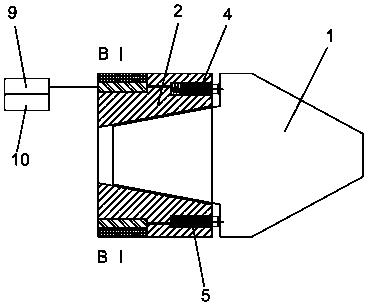
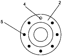
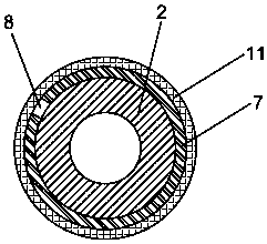
[0027] Such as Figure 1-5 As shown, a piezoelectric-driven electric spindle chip detection device for CNC machine tools, including a fixture body 2 for clamping a tool handle 1, a tapered groove is provided in the fixture body 2, and the fixture body 2 is coaxially fixed At one end of the electric spindle of the CNC machine tool.

[0028] A number of piezoelectric ceramic blocks that can extend out of the clamp body 2 are evenly distributed in the end of the fixture body 2 that is in contact with the tool handle 1. The end of the piezoelectric ceramic block that can extend out of the clamp body 2 is provided with a conductive touch terminal 3. The electric ceramic block includes a movable piezoelectric ceramic block 4 and seven fixed piezoelectric ceramic blocks 5, the conductive touch terminal 3 at the end of the movable piezoelectric ceramic...


PUM


Abstract

The invention relates to the technical field of machine tool parts, in particular to a piezoelectric drive type electric spindle chip mingling detection device used for a numerical control machine tool. The piezoelectric drive type electric spindle chip mingling detection device comprises a conical clamp body used for clamping a tool handle and is characterized in that piezoelectric ceramic blockswhich can stretch out of the clamp body after being electrified are evenly distributed in the end, making contact with the tool handle, of the clamp body; the ends, being capable of stretching out ofthe clamp body, of the piezoelectric ceramic blocks are provided with electric conduction touch terminals; and the piezoelectric ceramic blocks include one movable piezoelectric ceramic block and multiple fixed piezoelectric ceramic blocks, and different electric properties are applied to the electric conduction touch terminals at the end portions of the fixed piezoelectric ceramic block and themovable piezoelectric ceramic blocks. During tool feeding of the numerical control machine tool, whether iron chips are mingled between the faces, making contact with the two end faces and two positions of a conical face of the tool handle clamp installed on the electric spindle of the numerical control machine tool, of the tool handle or not is detected, the detected alarming critical value can be preset, the numerical value is stable, and the detection accuracy, stability and reliability are improved.

Description

technical field [0001] The invention relates to the technical field of machine tool components, in particular to a piezoelectric-driven electric spindle chip detection device for a numerically controlled machine tool. Background technique [0002] CNC machine tools are the main machine tools of the equipment manufacturing industry, and their technical level represents the development level of a country's manufacturing industry. The machining center is the first important member of the CNC machine tool. Due to the concentration of processes and automatic tool change in the machining center, the time for clamping, measuring and machine tool adjustment of the workpiece is reduced, so that the cutting time of the machine tool reaches about 80% of the machine tool start-up time (only 15-20% for ordinary machine tools); at the same time It also reduces the workpiece turnover, handling and storage time between processes, shortens the production cycle, and has obvious economic ef...

Claims


Application Information

Patent Timeline
Patent Type & Authority Applications(China)
IPC IPC(8): B23Q17/00B23Q11/00
CPCB23Q11/0089B23Q17/00
Inventor 柴永生李林刘宇航刘咪闵晓晨张茂源卫尚涛王昌辉陈义保
Owner YANTAI UNIV
Learn More