Installation method of water injection pump station and corresponding motor and water injection pump integrated unit

An installation method and water injection pump technology, which are applied in the direction of pump devices, electric components, machines/engines, etc., can solve the problems of installation environment restrictions, installation accuracy cannot be guaranteed, etc., to improve work performance, improve work intensity, and facilitate installation Effect

Pending Publication Date: 2020-01-17
泰安阳光动力电机有限公司
View PDF0 Cites 1 Cited by
  • Summary
  • Abstract
  • Description
  • Claims
  • Application Information

AI Technical Summary

Problems solved by technology

[0005] The purpose of the present invention is to provide an installation method of a water injection pump station and a corresponding integrated motor and water injection pump unit, so as to solve the problem that the installation accuracy of the above-mentioned existing direct drive water injection pump station cannot be guaranteed due to the limitation of the installation environment question

Method used


Image

  • Installation method of water injection pump station and corresponding motor and water injection pump integrated unit
  • Installation method of water injection pump station and corresponding motor and water injection pump integrated unit
  • Installation method of water injection pump station and corresponding motor and water injection pump integrated unit

Examples


Embodiment 1

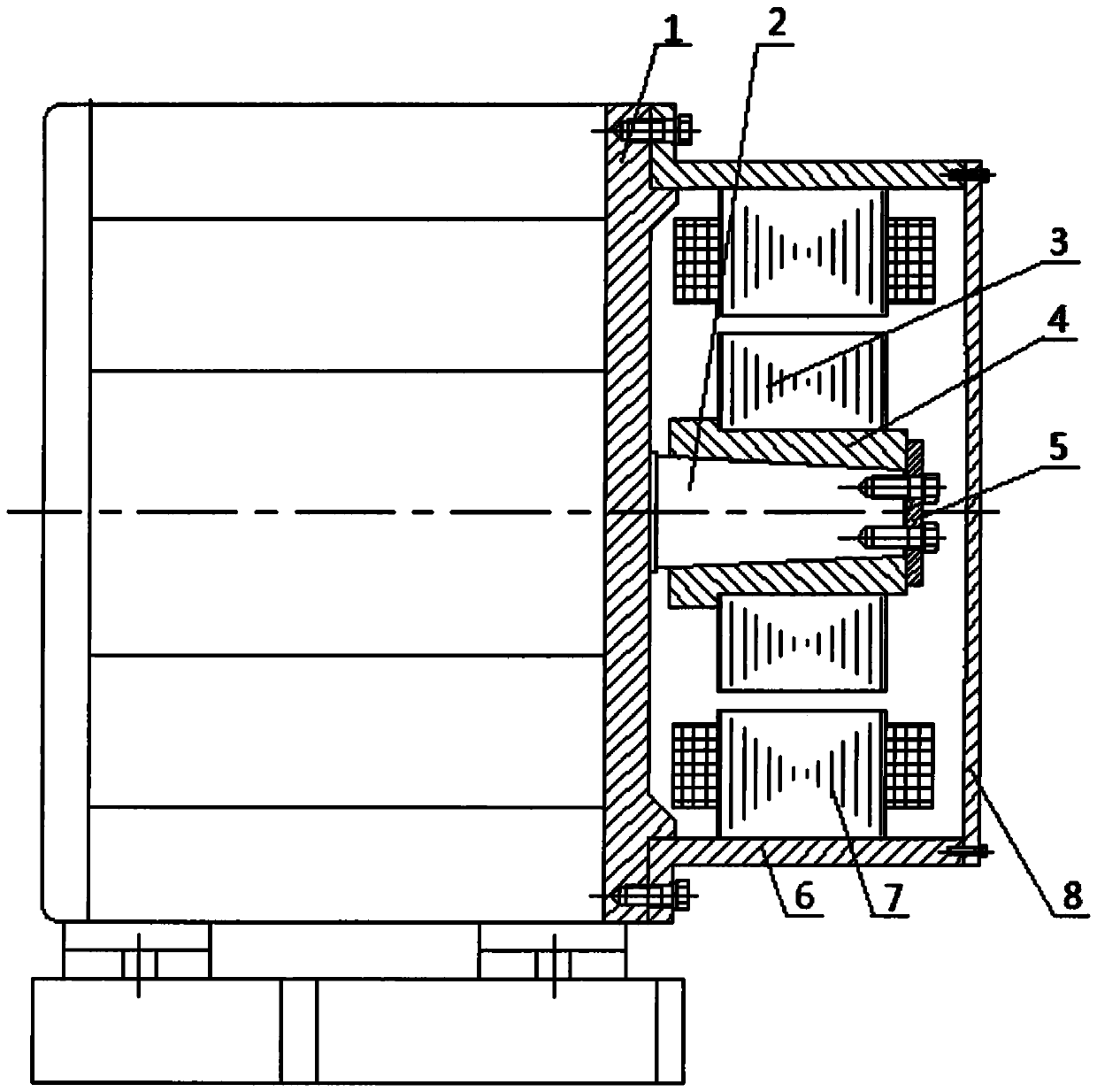
[0032] This embodiment provides an installation method for a water injection pump station. The installation method includes the following steps: firstly, process the end cap of the water injection pump with a shaft end to a stop, and install the water injection pump to the oil production place of the oil field; secondly, fix the motor The rotor sleeve of the rotor is coaxially fixed and installed on the shaft of the water injection pump; again, the end of the motor casing with the motor stator fixed inside is machined into a seam that matches the seam of the end cover, and the seam part of the end cover and the motor The spigot part of the casing is matched and fixedly connected; finally, the protective cover is fixed at the other end of the motor casing.

[0033] Corresponding to the installation method of the above-mentioned water injection pump station, this embodiment also provides an integrated motor and water injection pump unit, such as figure 1 As shown, it includes a ...

Embodiment 2

[0038] This embodiment provides another connection method between the water injection pump shaft 2 and the rotor sleeve 4 in Embodiment 1, such as figure 2As shown, the shaft 2 of the water injection pump adopts a spline shaft, and the hole of the rotor sleeve 4 adopts a spline hole that is coaxial with the spline shaft and cooperates with each other. In the hole, the error caused by the axis deviation during the installation process can also be avoided. There is a pressure plate 5 at the end of the rotor sleeve 4. The outer dimension of the pressure plate 5 is larger than the maximum aperture of the spline hole. The pressure plate 5 is fixedly connected with the water injection pump shaft 2 by screws. , so that the pressure plate 5 can press the rotor sleeve 4 on the water injection pump shaft 2, the rotor sleeve 4 and the water injection pump shaft 2 mesh with each other and transmit torque, and the weight of the rotor 3 is supported by the water injection pump bearing, maki...

Embodiment 3

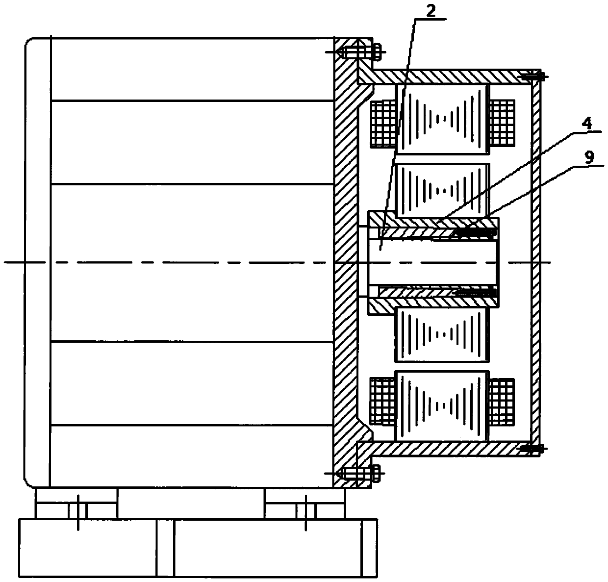
[0040] This embodiment provides another connection method between the water injection pump shaft 2 and the rotor sleeve 4 in Embodiment 1, such as image 3 As shown, the shaft 2 of the water injection pump adopts a cylindrical shaft, and the hole of the rotor sleeve 4 adopts a cylindrical hole that is coaxial with the cylindrical shaft and cooperates with each other. There is an expansion sleeve 9 inside the cylindrical rotor sleeve, and the two are installed in the cylindrical hole together. It can also avoid the error caused by the axis deviation in the installation process. By tightening the screws of the expansion sleeve 9, the inner diameter of the expansion sleeve 9 is reduced and the outer diameter is increased, so that the rotor sleeve 4 and the water injection pump shaft 2 are tightly connected together. At the same time The pressure plate 6 is also omitted, the rotor sleeve 4 is locked with the water injection pump shaft 2 and transmits torque, and the weight of the r...


PUM


Abstract

The invention provides an installation method of a water injection pump station and a corresponding motor and water injection pump integrated unit. The corresponding motor and water injection pump integrated unit comprises a motor and a water injection pump which are connected, the connecting end of the water injection pump is provided with an end cover and an outwards extending water injection pump shaft, and the motor comprises a case. Stators are annularly distributed and fixed to the inner wall of the case along the circumferential direction, a rotor sleeve is arranged at the position of amiddle shaft in the case, and rotors are annularly distributed and fixed on the outer wall of the rotor sleeve along the circumferential direction. The rotor sleeve is coaxially matched and fixedly connected with the water injection pump shaft, the case is fixedly connected with the end cover, a protective cover is further fixed to the non-connecting end of the case, and the rotor and the statorare installed respectively. According to the present invention, the problem that the double-positioning installation is difficult during overall installation of the motor is solved; meanwhile, the front and rear bearings of the motor and the front and rear end covers of the motor are saved, so that the structure of the whole unit is more simplified, the size is smaller, the occupied space is smaller, and space is saved for the pump station.

Description

technical field [0001] The invention relates to the field of oilfield water injection equipment, in particular to a method for installing a water injection pump station and a corresponding integrated unit of a motor and a water injection pump. Background technique [0002] Oil field water injection is an important part of oil production. The power consumption of water injection system generally accounts for 40%-60% of the power consumption of oil field production. The cost of oil recovery in an oil field. [0003] In order to solve the problems existing in the existing water injection pump station, patent No. ZL2018206610565 discloses a direct-drive water injection pump station, which proposes a new structure of the water injection pump station, removing the belt drive mechanism set up in the water injection pump station, and the motor is directly connected to the The water injection pump is connected, and the transmission link of the water injection pump is simplified, whi...

Claims


Application Information

Patent Timeline
Patent Type & Authority Applications(China)
IPC IPC(8): H02K7/14H02K5/04F04D13/06F04D29/043
CPCF04D13/06F04D29/043H02K5/04H02K7/14
Inventor 马力马善振
Owner 泰安阳光动力电机有限公司
Why Eureka
Try Eureka