
A method for data collection and management of electrical equipment

A technology of data collection and management methods, applied in electrical components, circuit devices, instruments, etc., can solve the problems of information lag, reduced work efficiency, low level of intelligence, etc., and achieves the effect of simple operation, stable performance and convenient installation

Active Publication Date: 2020-12-25
云南电网有限责任公司信息中心
View PDF8 Cites 0 Cited by
  • Summary
  • Abstract
  • Description
  • Claims
  • Application Information

AI Technical Summary

Problems solved by technology

3 discloses a management system for electric power measuring instruments, including a collection control layer, a communication layer, a business layer, and a comprehensive application layer; Efficiency, cooperation and improvement, combined with the application of RFID radio frequency identification technology has greatly improved the automation of warehouse management, so that under normal circumstances, the entire operation process from storage to delivery does not require manual operation and intervention, which not only saves labor and improves Improve work efficiency and greatly improve the accuracy of the operation, and combined with the application of RFID radio frequency identification technology, the collection and acquisition of information are completely executed by the system, and the synchronization of information and meter objects is realized, which not only greatly simplifies the entire collection and acquisition process, but also It also greatly improves the efficiency and accuracy. However, the researchers found that the intelligence level of the system is low, and the real-time transmission of data cannot be realized, which leads to the lag of information.
[0004] Patent No. CN108490835A discloses a method for data collection and management of power equipment. The data information of power equipment is collected through a signal collector, and the data information is subjected to multi-stage filtering and multi-stage amplification through a signal processing integrated circuit, and the high-precision The A / D conversion chip converts the analog quantity into a digital quantity and inputs it into the MSP430F5529 single-chip microcomputer. In this way, the accuracy of the data information reception is high, the accuracy is improved, and the collected data information is stored for easy query; the monitoring device is remotely real-time Monitoring can prevent the occurrence of safety accidents caused by failure to deal with failures in time and ensure the reliability of monitoring. However, researchers have found that this data collection method cannot realize automatic meter reading and automatic production of analysis reports, which improves human resources. workload, reducing work efficiency
[0005] Patent No. CN107037300A discloses a multi-channel data acquisition device for power systems, including a host computer, a voltmeter, an oscilloscope, a signal generator, a power supply module, a single-chip microcomputer, a CPLD, a logic channel control module, and a test needle. , an oscilloscope, a signal generator, a single-chip microcomputer, a CPLD, and a logic channel control module are connected to a power supply module, and the power supply control module provides multiple levels of voltages, and the CPLD is connected to the IO port of the single-chip microcomputer, and the IO port output of the single-chip microcomputer is used as a trigger signal of the CPLD; The logic channel control module is connected with CPLD, test bed of needles, multimeter, oscilloscope, and signal generator. This device can realize multi-channel signal acquisition at the same time, which improves signal acquisition efficiency and signal acquisition quality, and greatly reduces signal board testing. time, which improves work efficiency and saves labor costs, but the researchers found that after a long period of use, the equipment needs to be replaced, which greatly increases the cost of intelligent construction of the power network

Method used


Image

  • A method for data collection and management of electrical equipment

Examples


Embodiment Construction

[0028] The following will clearly and completely describe the technical solutions in the embodiments of the present invention with reference to the accompanying drawings in the embodiments of the present invention. Obviously, the described embodiments are only some, not all, embodiments of the present invention.

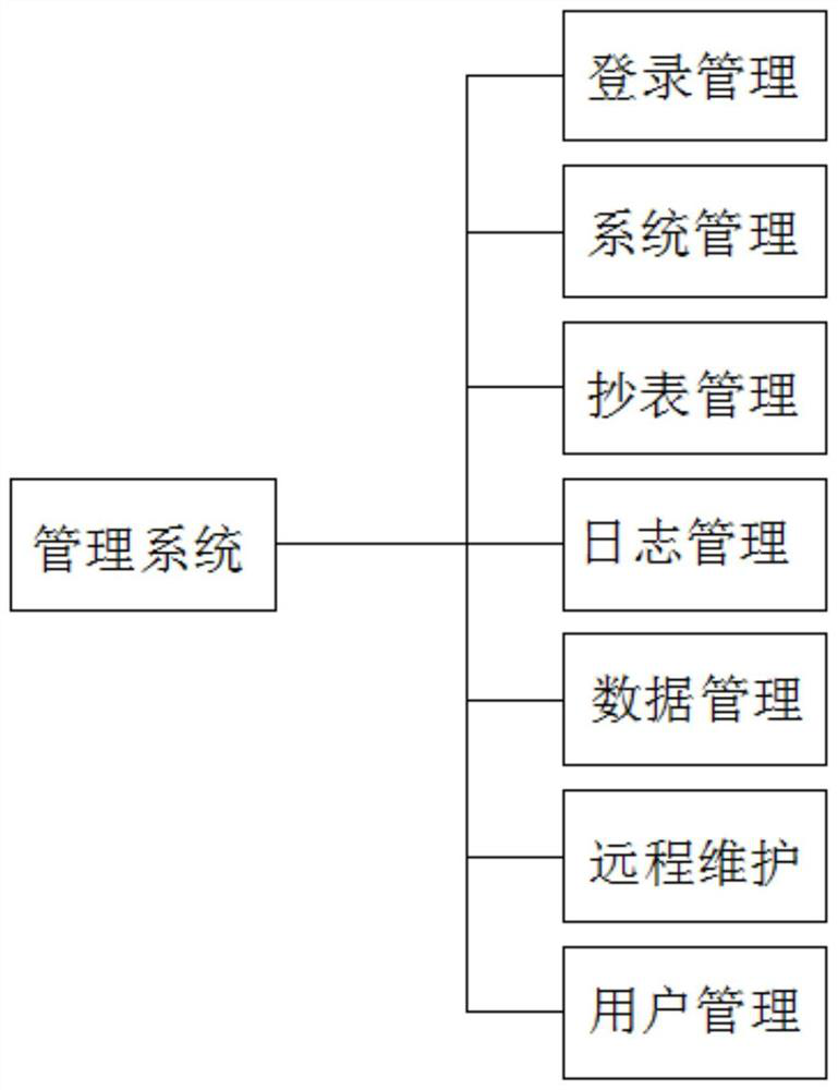
[0029] refer to figure 1 , a power equipment data collection and management method, comprising the following steps:

[0030] S1. Use the dedicated line provided by the communication company to apply for a fixed IP address and connect it to the GPRS network to form a GPRS network system. By configuring a fixed IP address and connecting to the GPRS network, large-capacity data collection and application can be realized. Through the GPRS network system , the power department can transmit the power system data collected by industrial and civil meters to the centralized monitoring center at the prefectural, municipal and provincial levels in real time, so as to realize th...


PUM


Abstract

The invention discloses a power equipment data acquisition and management method, and the method comprises the following steps: S1, applying for and configuring a fixed IP address by adopting a special line provided by a communication company, and connecting the IP address with a GPRS network to form a GPRS network system; S2, constructing an electric power remote meter reading system on the basisof the GPRS network system; S3, installing a multifunctional meter and an electric power data terminal on a power grid, and performing data connection with the electric power remote meter reading system. According to the invention, the PDT-51 power data transmission terminal is added to an original multifunctional meter, so the remote meter reading can be achieved, and the labor cost is saved; meanwhile, the remote upgrading function can realize upgrading of the electric meter and the data transmission terminal, so the use cost of the product is saved, the terminal information flow and the operation cost are saved, real-time data transmission can be realized, the progress of intelligent power construction is accelerated, the data transmission quality is improved, real-time monitoring of power transformation equipment is facilitated, and the probability of danger is reduced.

Description

technical field [0001] The invention relates to the technical field of power equipment data collection, in particular to a power equipment data collection and management method. Background technique [0002] With the continuous advancement of the construction of electric power intelligent network, the traditional multi-function meter cannot measure all the commonly used power parameters in the three-phase power grid system with high precision, and cannot meet the demand for real-time transmission of information. There is a lot of room for improvement and limitations. [0003] At present, there are more and more researches on data acquisition of power equipment. Patent No. CN201110341080.3 discloses a management system for power measuring instruments, including acquisition control layer, communication layer, business layer, and comprehensive application layer; the management system has changed the traditional The operation method requires the restriction of multiple people to...

Claims


Application Information

Patent Timeline
Patent Type & Authority Patents(China)
IPC IPC(8): H02J13/00G08C17/02
CPCG08C17/02
Inventor 郭威李寒箬罗震宇陈何雄和悦谢林江杭菲璐
Owner 云南电网有限责任公司信息中心
Learn More