Gas type super-fine dry powder automatic fire extinguishing system

An automatic fire extinguishing system and ultra-fine dry powder technology, applied in fire rescue, fire alarms that rely on radiation, and measuring devices, can solve problems such as difficult maintenance, disasters, and large protection space, and achieve continuous injection pressure. Stable, stable physical and chemical properties, little effect of ambient temperature

Inactive Publication Date: 2020-01-24
龚继海
View PDF5 Cites 0 Cited by
  • Summary
  • Abstract
  • Description
  • Claims
  • Application Information

AI Technical Summary

Problems solved by technology

At present, highways and railway tunnels basically use foam manual fire extinguishing. It is difficult to maintain in high cold and water-scarce areas. In addition, the traffic flow of highways is generally large. Once a fire occurs in the tunnel, the vehicles will be congested and the smoke will fill the air. Manual fire extinguishing facilities are basically useless. Professional Firefighters, vehicles, and fire extinguishing facilities are difficult to arrive in time, and often miss the best time to extinguish the fire, causing disasters
However, there is still the problem that the electric fire extinguishing in the utility tunnel cannot be extinguished with water
[0004] Cable trenches, cable interlayers, cable shafts, power distribution cabinets, and oil-immersed transformers in the power transformation industry are the most repr

Method used


Image

  • Gas type super-fine dry powder automatic fire extinguishing system
  • Gas type super-fine dry powder automatic fire extinguishing system
  • Gas type super-fine dry powder automatic fire extinguishing system

Examples


Example Embodiment

[0028] The present invention will be further described below in conjunction with the drawings and embodiments. The present invention includes but is not limited to the following embodiments.

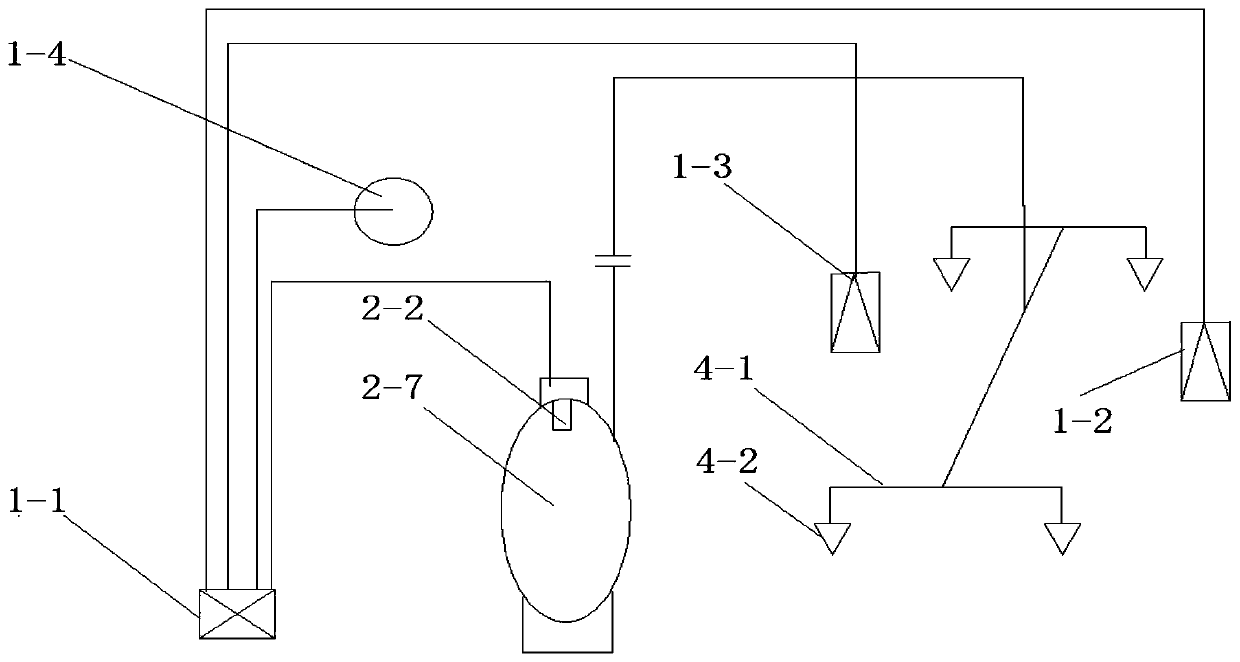
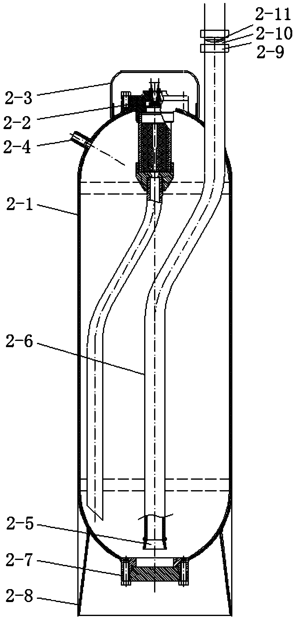
[0029] The invention consists of two parts: a gas-type superfine dry powder automatic fire extinguishing equipment and a fire induction alarm system. The fire induction alarm system belongs to a conventional fire detection system with strong technical versatility and is not the core content of the invention. Among them, the gas-type ultra-fine dry powder automatic fire extinguishing equipment uses the gas generated by the combustion of insensitive gas generating agents to drive the ultra-fine dry powder along the pipeline to the fire source. The gas-fired ultrafine dry powder automatic fire extinguishing equipment includes a gas generator, a fire extinguishing agent, a dry powder tank, a pressure gauge, a rupture disc, a holder, a pipeline and a nozzle.

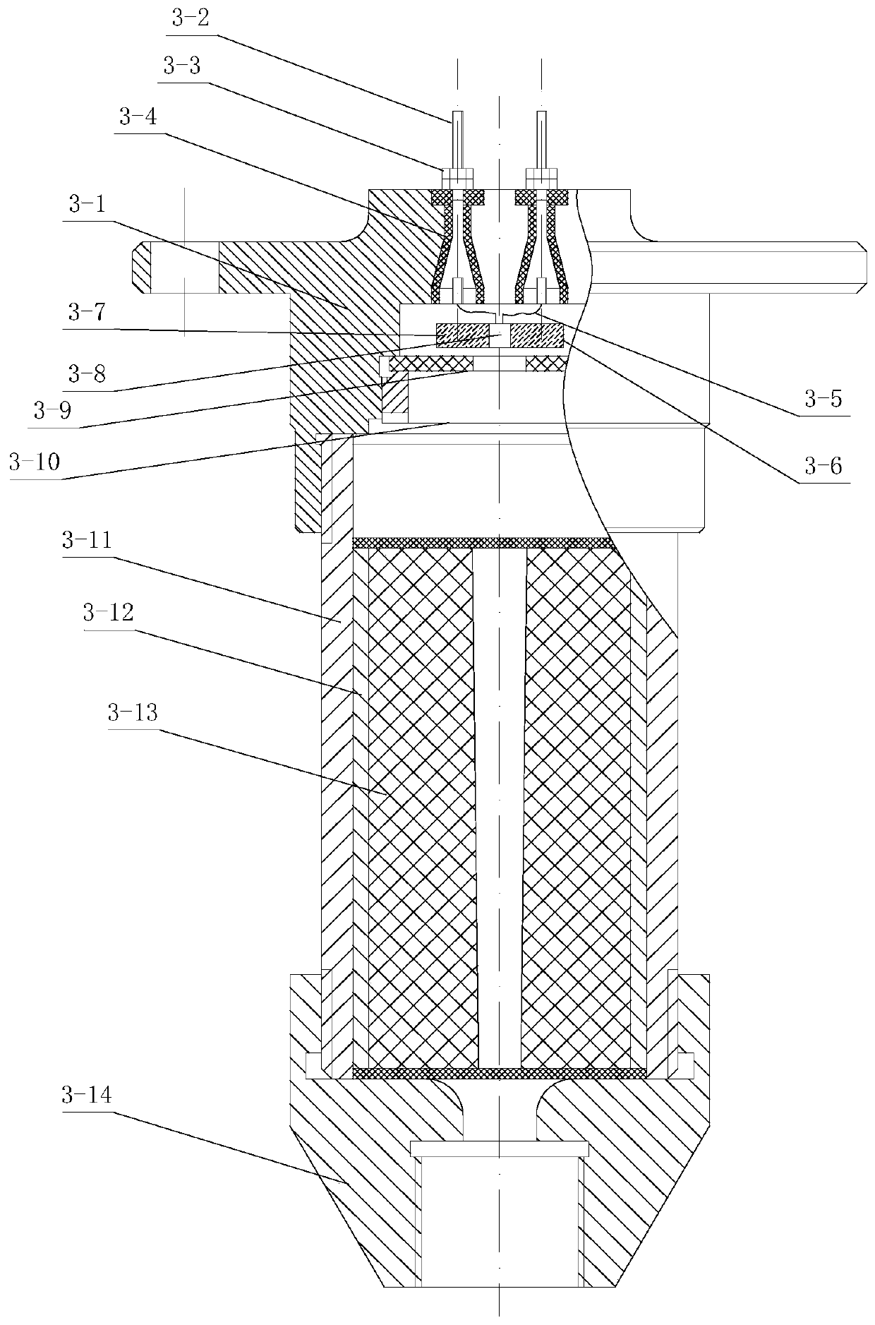
[0030] The gas generator includes a g...


PUM


Abstract

The invention provides a gas type super-fine dry powder automatic fire extinguishing system which comprises a gas generator, a dry powder tank, a rupture disk, a pipeline and a nozzle. The dry powdertank is filled with a dry powder fire extinguishing agent. The top end of the dry powder tank is provided with the gas generator. One end of the pipeline is located in the dry powder tank and faces the bottom of the dry powder tank, and the other end of the pipeline is located outside the dry powder tank and is connected with the nozzle. The interior of the pipeline is blocked by the rupture disk.The gas generator comprises a gas generating grain and an igniting device. The igniting device receives a triggering signal sent out by a fire disaster sensing and alarming system and ignites the gasgenerating grain. Gas and dry powder are sufficiently mixed to form gas-solid two-phase flow. When the pressure reaches the relief pressure of the rupture disk, the rupture disk is opened, and the gas-solid two-phase flow is sprayed out of the pipeline through the nozzle. No pressure or valve or complicated power device exists in the dry powder tank at ordinary times, instant triggering and rapidfire extinguishing are performed in a fire behavior, and the dry powder jet pressure is high, continuous and stable.

Description

Technical field [0001] The invention relates to an automatic fire extinguishing system, belonging to the technical field of fire extinguishing equipment. Background technique [0002] In the petrochemical industry, many products are flammable and explosive. Large-scale fires are prone to occur under lightning, static electricity, impact, leakage, line aging, and accidental sparks. Because water cannot be used to extinguish fires, portable dry powder fire extinguishers and pushers are commonly used. Car dry powder fire extinguishers, but once a fire occurs, it is difficult for people to approach the fire extinguishing device. At present, the fire extinguishing devices that can be automatically triggered are all based on sprinklers and cannot be used in the petrochemical field. Although the high-pressure gas cylinder dry powder fire extinguisher can be automatically triggered and used in the petrochemical field, it is expensive and difficult to maintain, and due to its many valves ...

Claims


Application Information

Patent Timeline
IPC IPC(8): A62C3/06A62C31/02A62C37/10G08B17/12G01D21/02
CPCA62C3/06A62C31/02A62C37/10G01D21/02G08B17/12
Inventor 龚继海
Owner 龚继海
Why Eureka
Try Eureka