Flow guide device, gas mixing equipment and gas treatment system

A technology of diversion device and gas mixing, applied in gas treatment, fluid mixer, mixer and other directions, can solve the problem of uneven distribution of flue gas flow field, achieve convenient assembly and maintenance, high integration, and improve the effect Effect

Pending Publication Date: 2020-01-24
MCC CAPITAL ENGINEERING & RESEARCH
View PDF0 Cites 0 Cited by
  • Summary
  • Abstract
  • Description
  • Claims
  • Application Information

AI Technical Summary

Problems solved by technology

[0007] The purpose of the present invention is to provide a diversion device, a gas mixing device and a gas treatment system to solve the problem of uneven distribution of the flue gas flow field in the SCR denitrification inlet flue

Method used


Image

  • Flow guide device, gas mixing equipment and gas treatment system
  • Flow guide device, gas mixing equipment and gas treatment system
  • Flow guide device, gas mixing equipment and gas treatment system

Examples


Embodiment approach 1

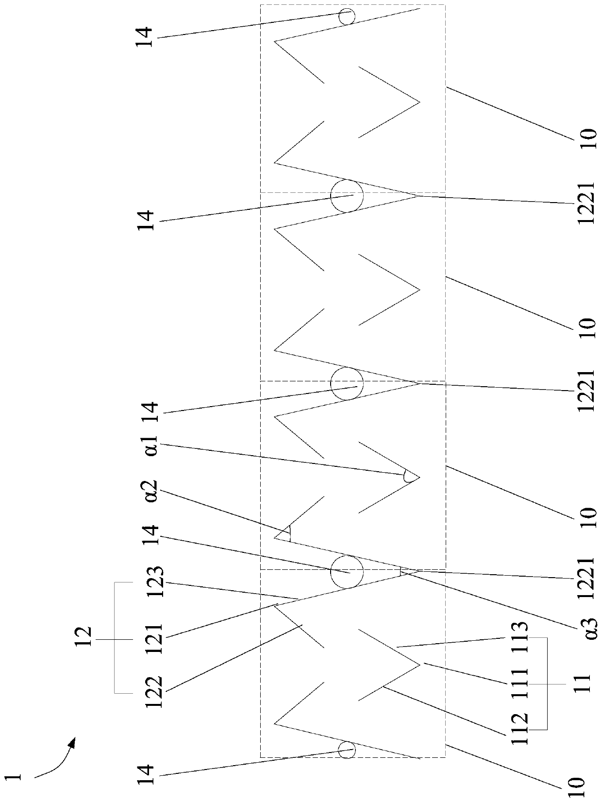
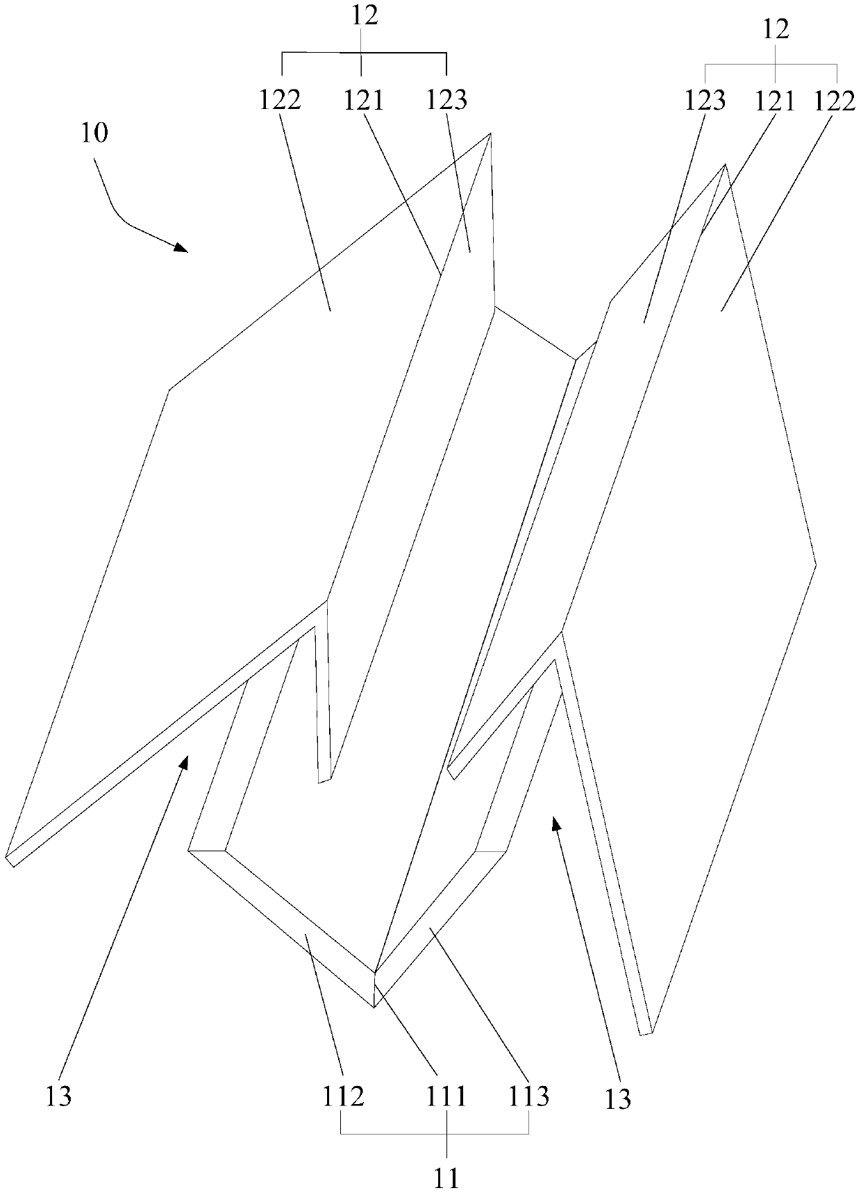
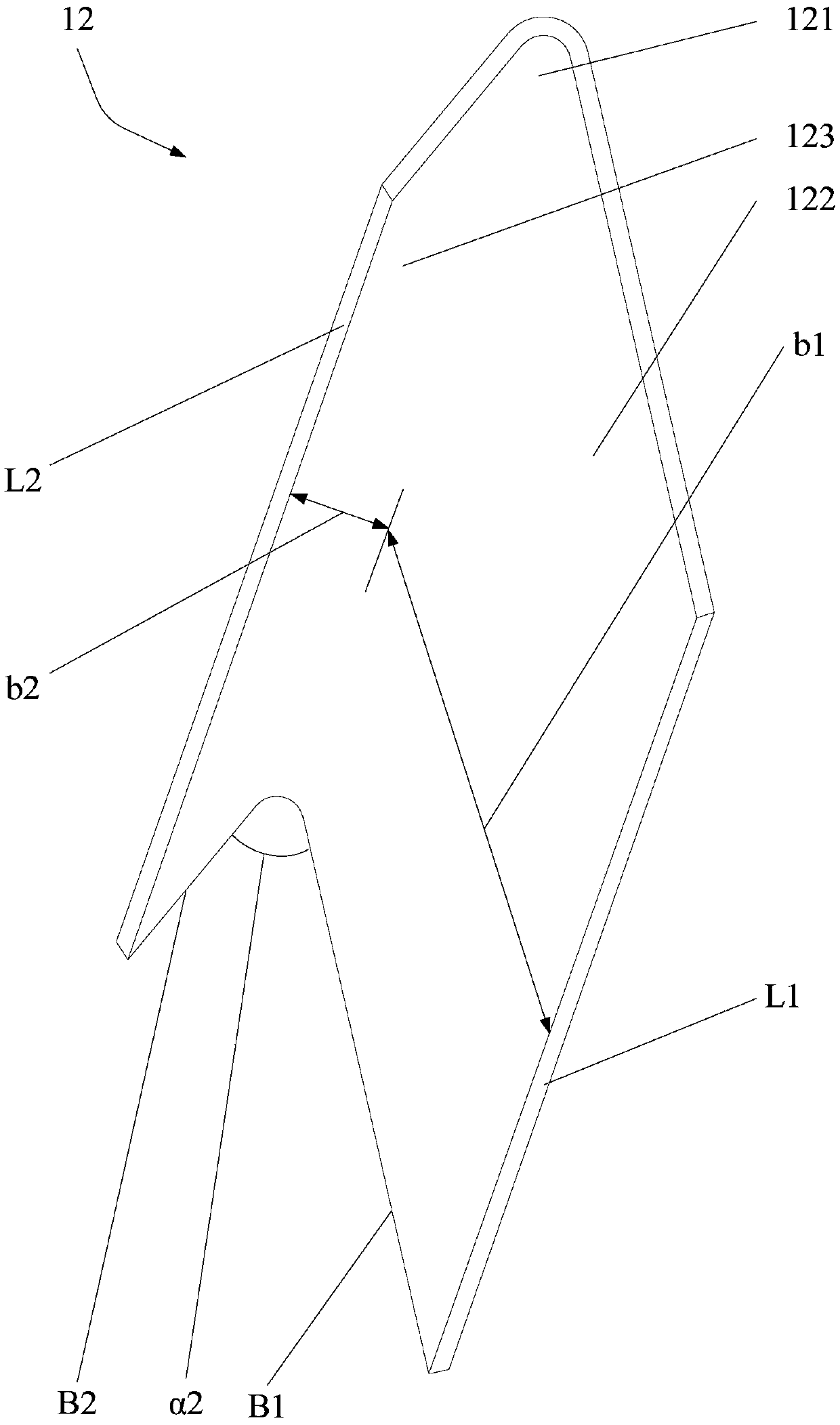
[0040] The present invention provides a flow guiding device 1, please refer to Figure 1 to Figure 6 , the flow guide device 1 includes a plurality of flow guide structures 10 arranged side by side, the flow guide structure 10 has a first flow guide piece 11 and two second flow guide pieces 12 symmetrically arranged on both sides of the first flow guide piece 11 , A gap 13 for fluid flow is formed between the first flow guide 11 and the second flow guide 12; wherein, the first flow guide 11 has a first bending portion 111, and the second flow guide 12 has a second In the bending portion 121 , the opening of the first bending portion 111 is disposed toward the opening of the second bending portion 121 .

[0041] The flow guide device 1 divides, guides and merges the fluid through the first flow guide 11 and the second flow guide 12, so that the fluid collides and disturbs during the movement, thereby forming a turbulent flow effect, and finally making the flow The gas passing ...

Embodiment approach 2

[0061] Such as Figure 1 to Figure 7 As shown, the present invention provides a gas mixing device 2, which includes a flow guiding device 1 and a gas delivery mechanism 21, and the gas delivery mechanism 21 has a plurality of gas injection parts 211 arranged at intervals. Wherein, the flow guiding device 1 is disposed on the same side of the plurality of gas injection parts 211 , and the gas injection parts 211 are disposed opposite to the first bending part 111 . The specific structure, working principle and beneficial effects of the flow guiding device 1 in this embodiment are the same as those in the first embodiment, and will not be repeated here.

[0062] In the gas mixing device 2 provided by the present invention, the gas injection part 211 is arranged opposite to the first bending part 111, and then the gas injection part 211 is used to inject gas onto the first flow guide member 11 of the flow guide structure 10 in the flow guide device 1 , so that the first bending ...

Embodiment approach 3

[0068] Such as Figure 1 to Figure 8 As shown, the present invention provides a gas treatment system 3 .

[0069] Specifically, the gas processing system 3 includes a gas channel 31 and a gas mixing device 2, and the gas mixing device 2 is arranged in the gas channel 31; wherein, after the first gas enters the gas channel 31 along the fluid flow direction F, it can be combined with a plurality of gases The second gas ejected from the ejection part 211 is uniformly mixed through the flow guiding device 1 . The specific structure, working principle and beneficial effects of the gas mixing device 2 in this embodiment are the same as those in Embodiment 2, and will not be repeated here.

[0070] In a specific application environment, the gas channel 31 is a flue, the gas delivery mechanism 21 is an ammonia gas pipeline, the gas injection part 211 is a nozzle, the first gas is flue gas, and the second gas is ammonia gas. The working principle and working process of the gas treatm...


PUM


Abstract

The invention discloses a flow guide device, gas mixing equipment and a gas treatment system. The flow guide device comprises a plurality of flow guide structures arranged side by side, each flow guide structure is provided with a first flow guide piece and two second flow guide pieces symmetrically arranged on the two sides of the first flow guide piece; and gaps allowing fluid to circulate are formed between the first flow guide piece and the second flow guide pieces; the first flow guide piece is provided with a first bent part, each of the second flow guide piece is provided with a secondbent part, and an opening of the first bent part is designed to face an opening of each second bent part. According to the flow guide device, fluid is divided, guided and converged through the first flow guide piece and the second flow guide pieces, so that the fluid collides and disturbs in the moving process, then turbulence effect is formed, and finally gas flowing through the flow guide deviceis more uniform and stable.

Description

technical field [0001] The invention relates to the technical field of flue gas denitrification, in particular to a diversion device, gas mixing equipment and a gas treatment system. Background technique [0002] In recent years, in the face of the increasingly severe environmental protection situation, my country's NOx emissions from non-electric industries such as steel, cement, and glass x Concentration has been comprehensively carried out in-depth management. The current mainstream technology is the combination of low nitrogen combustion and SCR (Selective Catalytic Reduction) to achieve NO x Ultra-low emissions require improved SCR denitrification efficiency. [0003] In the prior art, by optimizing the flue gas flow field and the design of the ammonia nozzle, the NH 3 / NO x The method of mixing uniformity is considered to be the most economically feasible method. The methods for uniform mixing of flue gas and ammonia gas generally include increasing the density of...

Claims


Application Information

Patent Timeline
Patent Type & Authority Applications(China)
IPC IPC(8): B01D53/90B01D53/56B01F5/00
CPCB01D53/90B01D53/56B01D2251/2062B01D2258/0283B01F25/4231
Inventor 邱明英王建华崔岩张宇鑫朱繁任乐郝景章
Owner MCC CAPITAL ENGINEERING & RESEARCH
Why Eureka
Try Eureka