High-efficiency milling and flattening machine

A milling and flattening machine and high-efficiency technology, applied in milling machine equipment, milling machine equipment details, metal processing machinery parts, etc., can solve the problems of low processing efficiency and cumbersome processing process, so as to improve processing efficiency, improve recycling efficiency, and improve feeding efficiency. high effect

Active Publication Date: 2020-10-02
天津宇仁金属制品有限公司
View PDF5 Cites 0 Cited by
  • Summary
  • Abstract
  • Description
  • Claims
  • Application Information

AI Technical Summary

Problems solved by technology

[0004] The above-mentioned existing technical solutions have the following defects: when the above-mentioned flat milling machine is in use, it is necessary to manually place the workpiece between the two cutting tools, and then manually remove the workpiece after processing, so that the entire processing process is more complicated. Complicated, low processing efficiency

Method used


Image

  • High-efficiency milling and flattening machine
  • High-efficiency milling and flattening machine
  • High-efficiency milling and flattening machine

Examples


Embodiment Construction

[0031] The present invention will be further described in detail below in conjunction with the drawings.

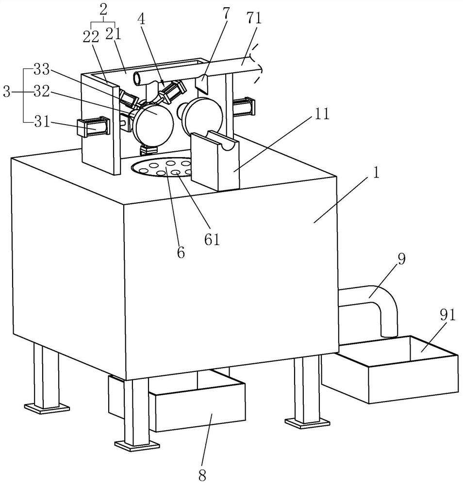
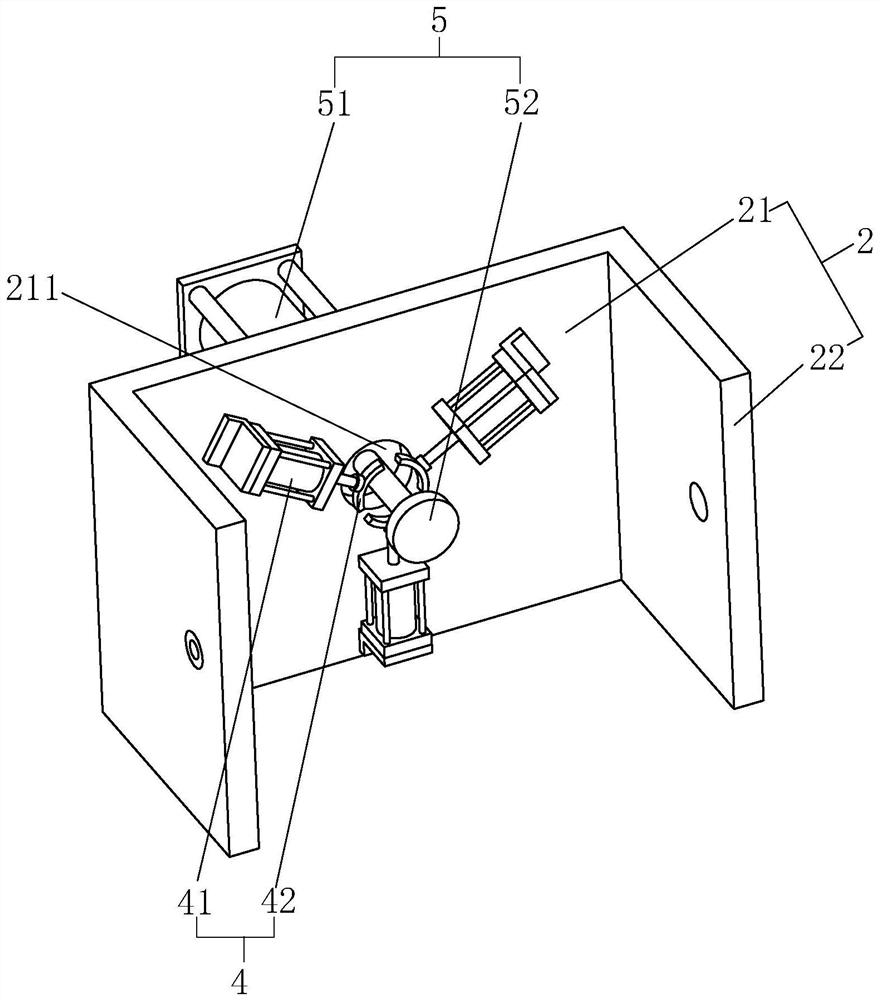
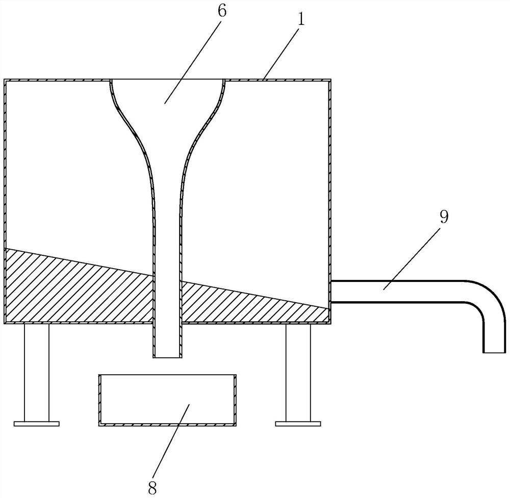
[0032] A high-efficiency milling machine, combining figure 1 with figure 2 , Including the machine body 1, the upper surface of the machine body 1 is fixedly provided with a support frame 2, and the support frame 2 is provided with a feeding part 5 for facilitating workpiece feeding, a clamping part 4 for clamping the workpiece, and for processing the workpiece In the processing assembly 3, the upper surface of the body 1 is provided with a discharge channel 6. During processing, the workpiece is moved close to the support frame 2 by the feeder 5, and the workpiece is clamped by the clamping member 4. Then the workpiece is processed by the workpiece. After the workpiece is processed, the clamping member 4 is released, so that The workpiece falls naturally, enters the discharge channel 6, and falls along the discharge channel 6, so that the overall efficiency of loading, pro...


PUM


Abstract

The invention relates to a high-efficiency flat milling machine. The key point of the technical scheme is a high-efficiency flat milling machine, the high-efficiency flat milling machine comprises a machine body, a supporting frame is fixedly arranged on the surface of the machine body, a group of processing components which are facing each other to flat milling a workpiece are fixedly arranged onthe supporting frame, a plurality of clamping parts which are used for clamping the workpiece are fixedly arranged on the supporting frame, the clamping parts and the processing components are located at a side face adjacent the supporting frame, the supporting frame is fixedly provided with a feeding part, the feeding part comprises a feeding driving cylinder which is fixed with the supporting frame and a taking magnet which is fixed with a piston rod of the feeding driving cylinder, the piston rod of the feeding driving cylinder is located in the middle of the two groups of the processing components and is perpendicular to a connecting line between the two groups of the processing components, a shrinkage groove is arranged at the position where the supporting frame is directly facing the taking magnet, the groove depth of the shrinkage groove is larger than the thickness of the taking magnet, the machine body is fixedly provided with a temporarily placed table for temporarily placing workpieces, and the temporarily placed table is located in the front of the feeding driving cylinder, so that the effect that the processing efficiency is improved is achieved.

Description

Technical field [0001] The invention relates to the technical field of mechanical processing, in particular to a high-efficiency flat milling machine. Background technique [0002] At present, when assembling gears on a shaft with a smaller shaft diameter, a flat notch is generally used instead of the keyway. The flat notch is the shaft milling, and the equipment for processing this structure is called a flat milling machine. [0003] The existing Chinese patent with the authorized announcement number CN206305883U discloses a flat milling machine with filtering function, which includes a device main body including a table and a box located below the table. The table has grooves. A bracket for installing cutting tools is arranged in the groove, a fuel injection pipe is arranged on the bracket, a cavity is arranged in the box, and a partition plate is arranged in the cavity. The partition plate divides the cavity into an adsorption chamber and a precipitation chamber. The chambers a...

Claims


Application Information

Patent Timeline
Patent Type & Authority Patents(China)
IPC IPC(8): B23C3/00B23C9/00B23Q3/08B23Q7/00B23Q11/00B23Q11/10
CPCB23C3/00B23C9/00B23Q3/08B23Q7/00B23Q11/0067B23Q11/10B23Q11/1069B23Q2703/04
Inventor 冯博洋牛明明
Owner 天津宇仁金属制品有限公司
Why Eureka
Try Eureka