
Beam shaping mechanism, laser source system and laser 3D printing equipment and method

A beam shaping and 3D printing technology, applied in the optical field, can solve the problems of incomplete melting of powder materials, single laser beam mode, low energy at the edge of the spot, etc., to avoid high intermediate overlap rate, expand functions, and improve product quality. Effect

Pending Publication Date: 2020-01-31
福建国锐中科光电有限公司
View PDF0 Cites 5 Cited by
  • Summary
  • Abstract
  • Description
  • Claims
  • Application Information

AI Technical Summary

Problems solved by technology

[0006] The purpose of the present invention is to solve the above-mentioned technical problems such as single laser beam mode provided by various types of equipment using laser light sources, and quality problems such as unmelted, high porosity or cracking, which are common in printed parts based on laser 3D printing technology
The energy density in the center of the spot is too large, forming a large temperature gradient with the heat-affected zone. The solidification of the molten pool and the heat-affected zone generate large internal stress, which is likely to cause deformation or cracking of the parts; the energy at the edge of the spot is low, resulting in incomplete melting of the powder material , leading to defects such as unmelted and pores

Method used


Image

  • Beam shaping mechanism, laser source system and laser 3D printing equipment and method
  • Beam shaping mechanism, laser source system and laser 3D printing equipment and method
  • Beam shaping mechanism, laser source system and laser 3D printing equipment and method

Examples


Embodiment Construction

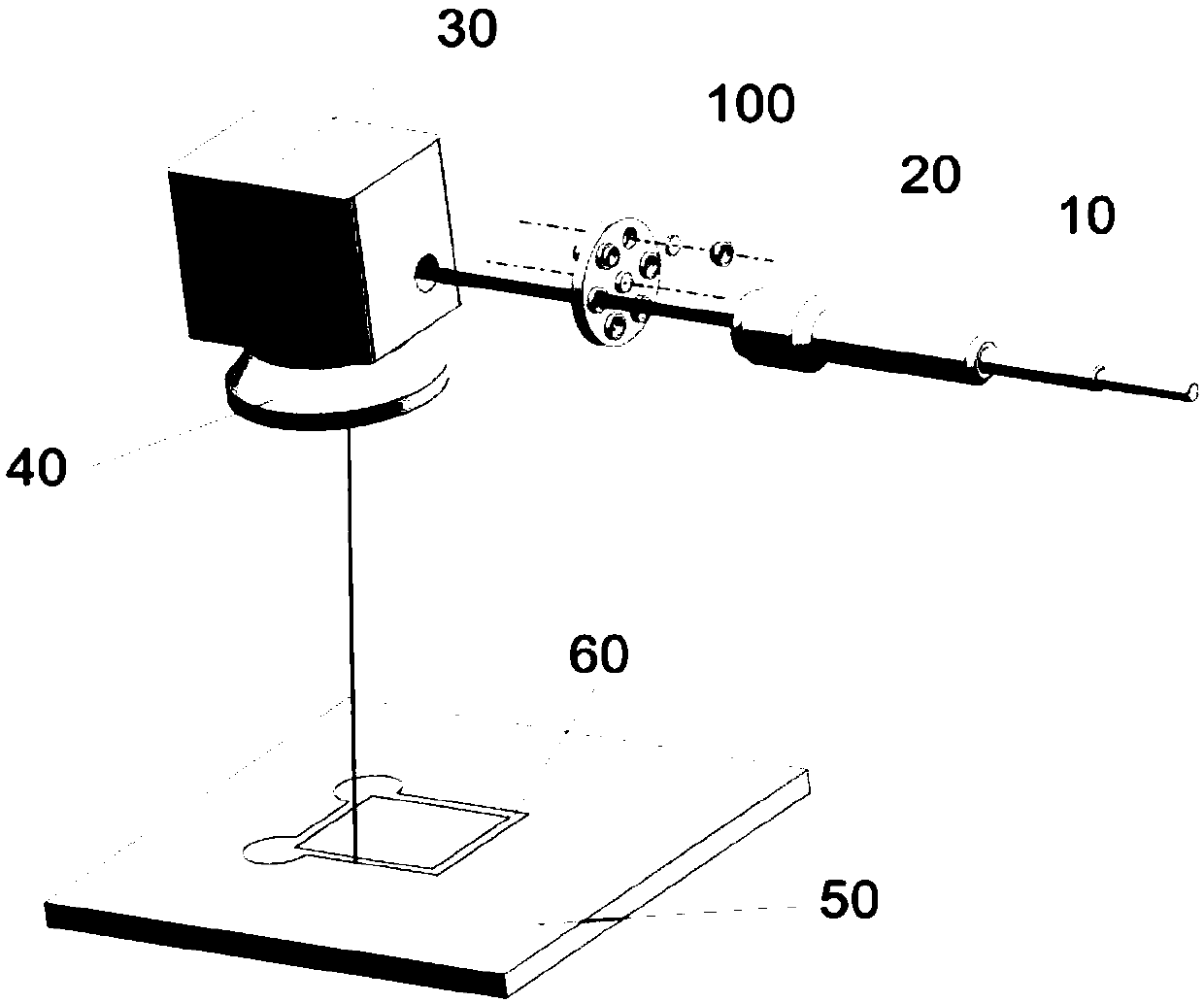
[0026] In order to make the object, technical solution and advantages of the present invention clearer, the present invention will be described in further detail below in conjunction with specific embodiments and with reference to the accompanying drawings. However, those skilled in the art know that the present invention is not limited to the drawings and the following embodiments.

[0027]

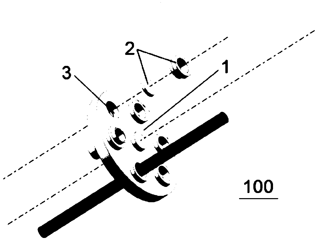
[0028] refer to figure 1 , the embodiment of the present invention proposes a beam shaping mechanism 100, which can be used in laser processing equipment such as laser 3D printing equipment, which includes a disc-shaped wheel 1 and one or more A beam shaper 2 for laser beam shaping, the runner 1 is provided with a plurality of holes 3 along the circumferential direction, the centerlines of the holes 3 are parallel to the central axis of the runner 1, and the centerlines of each hole 3 are parallel to the central axis of the runner 1. The distances between the central axes of the runne...


PUM


Abstract

The embodiment of the invention relates to a beam shaping mechanism used for laser processing equipment. The beam shaping mechanism comprises a rotary wheel and one or more beam shapers, and the beamshapers are arranged on the rotary wheel and are used for shaping laser beams emitted by a laser. The rotary wheel is provided with a plurality of holes in the circumferential direction. The center lines of the holes are parallel to the center shaft of the rotary wheel. The distances between the center lines of all the holes and the center shaft of the rotary wheel are equal. The beam shapers arearranged at the holes. The optical axes of the beam shapers coincide with the center lines of the holes where the beam shapers are located. Through the beam shaping mechanism, the condition that a single-mode laser beam is not suitable for an actual workpiece is avoided, and laser processing efficiency and product quality are improved.

Description

technical field [0001] The invention belongs to the field of optical technology, and in particular relates to a beam shaping mechanism, a laser light source system, and a laser 3D printing device and method. Background technique [0002] The laser beam emitted by the laser light source is a Gaussian beam, which needs to be shaped according to the actual situation. At present, most of the laser beams provided by various types of equipment using laser light sources, including laser processing equipment, have a single mode and cannot be suitable for processing. Practical requirements, especially in the field of additive manufacturing, are more problematic. [0003] Additive manufacturing, commonly known as 3D printing, integrates computer-aided design, material processing and forming technology, and is based on digital model files. Through software and numerical control system, special metal materials, non-metal materials and medical biological materials are processed according...

Claims


Application Information

Patent Timeline
IPC IPC(8): B29C64/153B29C64/268B22F3/105B28B1/00B33Y30/00
CPCB22F3/105B28B1/001B29C64/153B29C64/268B33Y30/00Y02P10/25
Inventor 林文雄吴鸿春林紫雄翁文黄见洪戴殊韬李锦辉张政张震奇刘永德张梓涵
Owner 福建国锐中科光电有限公司
Learn More