
Tool residual stress testing system based on magnetic acoustic emission principle and method

A residual stress, testing system technology, applied in force/torque/work measuring instrument, force metering by measuring the change of magnetic properties of materials caused by applied stress, measuring device, etc., can solve the complicated operation, high cost, evaluation area Small and other problems, to achieve the effect of simple system structure, improved timeliness and easy operation

Inactive Publication Date: 2020-02-04
TSINGHUA UNIV +1
View PDF5 Cites 3 Cited by
  • Summary
  • Abstract
  • Description
  • Claims
  • Application Information

AI Technical Summary

Problems solved by technology

To deal with the testing of large quantities of small cutting tools, only sampling can be used for performance evaluation
At the same time, the tested tool will no longer be used. In terms of dynamic evaluation, destructive testing seems to be helpless
However, the commonly used non-destructive residual stress detection, such as X-ray diffractometer, is not conducive to industrial applications because of its cumbersome operation, small evaluation area, and high cost, and it cannot be used for large-scale testing.
[0005] The existing application of detecting residual stress by using the principle of magnetoacoustic emission is not common. In the research at home and abroad, many pairs of welding containers, train wheels, chariots, missiles and other large components have been tested for residual stress after heat treatment, but no Detection of Tool Residual Stress Using Magnetoacoustic Emission Method

Method used


Image

  • Tool residual stress testing system based on magnetic acoustic emission principle and method
  • Tool residual stress testing system based on magnetic acoustic emission principle and method
  • Tool residual stress testing system based on magnetic acoustic emission principle and method

Examples


Embodiment Construction

[0033] Embodiments of the present invention are described in detail below, examples of which are shown in the drawings, wherein the same or similar reference numerals designate the same or similar elements or elements having the same or similar functions throughout. The embodiments described below by referring to the figures are exemplary and are intended to explain the present invention and should not be construed as limiting the present invention.

[0034] The following describes the tool residual stress testing system and method based on the principle of magnetoacoustic emission according to the embodiments of the present invention with reference to the accompanying drawings. .

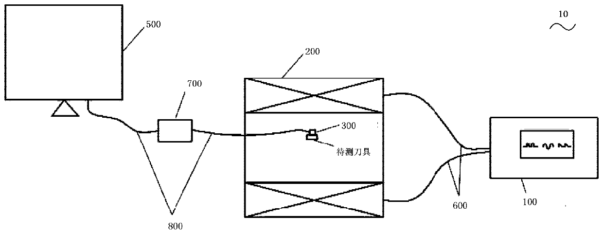
[0035] figure 1 It is a structural schematic diagram of a tool residual stress testing system based on the principle of magnetoacoustic emission according to an embodiment of the present invention.

[0036] Such as figure 1 As shown, the system 10 includes: a pulse power supply 100 , an excitati...


PUM


Abstract

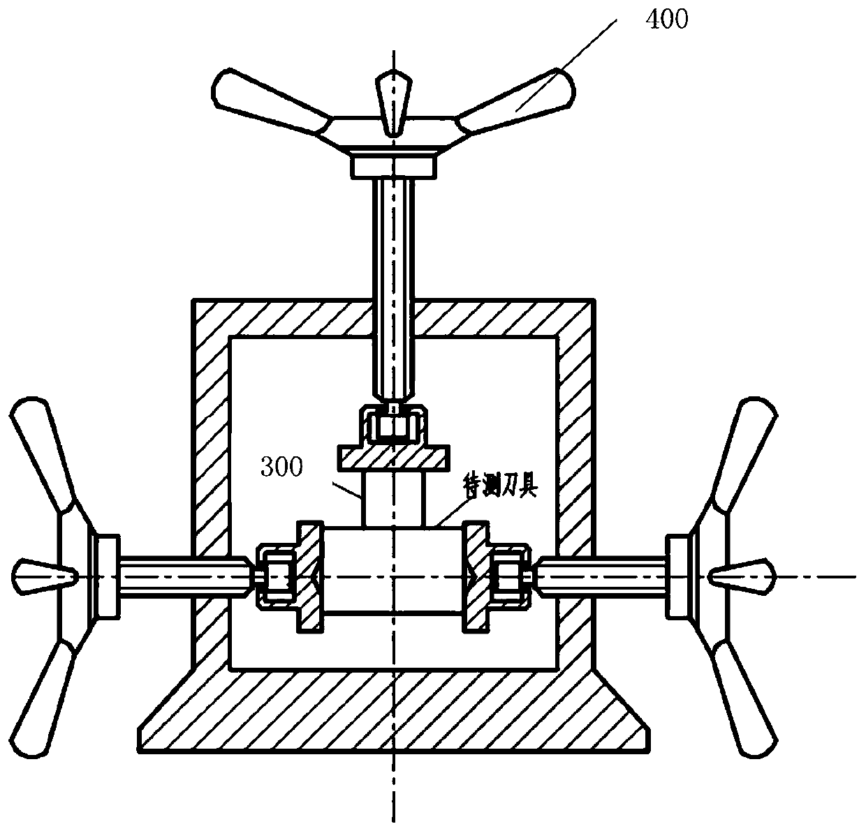
The present invention discloses a tool residual stress testing system based on magnetic acoustic emission principle and a method. The system includes a pulse power supply, an excitation coil, a test sensor, a fixture and a processor. The pulse power supply is connected with the excitation coil and provides preset current for the excitation coil. The test sensor and the tool to be tested are placedinside the excitation coil; the test sensor is affixed to the upper surface of the tool to be tested by the fixture; the excitation coil provides an alternating magnetic field for the tool to be tested; and the test sensor is used to collect stress wave generated by the tool to be tested under the influence of the magnetic field. The processor is connected with the test sensor and is used for receiving and processing the stress wave and outputting the residual stress level of the tool to be tested. The detection method of the system is more convenient and low-cost; the overall residual stresslevel is evaluated; and the timeliness is greatly improved with good accuracy.

Description

technical field [0001] The invention relates to the technical field of residual stress detection, in particular to a tool residual stress testing system and method based on the principle of magnetoacoustic emission. Background technique [0002] With the rapid development of industry, the demand for high-quality cutting tools is increasing. The tool will produce different degrees of residual stress after processing and after use. The level of residual stress directly affects the quality of the tool and the length of its life. Most of the current cutting tools are based on high-speed steel and cemented carbide, and the surface is coated with a hardened coating. The hardness is very high, and the traditional lossy residual stress measurement method is difficult to work. [0003] Existing residual stress detection methods are divided into two categories, destructive testing and nondestructive testing. In terms of destructive testing, the "ring core method" and "blind hole met...

Claims


Application Information

Patent Timeline
Patent Type & Authority Applications(China)
IPC IPC(8): G01L5/00G01L1/12
CPCG01L1/12G01L5/0047
Inventor 蔡志鹏许擎栋吴瑶季文张有强
Owner TSINGHUA UNIV
Learn More